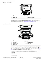

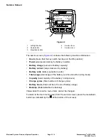
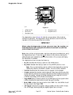
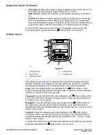


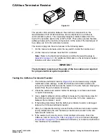

CAN bus
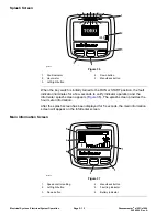
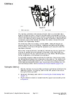
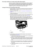
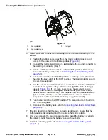
g338222
Figure 49
1.
DIAG connector
2.
Hour meter
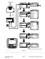
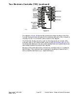
The machine controllers communicate with each other on a Controller Area
Network (CAN) bus system. Using this network allows full integration of all the
different electrical components of the machine, allowing them to operate together
as one. The CAN bus system reduces the number of electrical components and
connections used on the machine and allows the number of wires in the wire
harness to be significantly reduced.
The InfoCenter, lithium-ion battery controller (BMS - Battery Management
System) and TEC are on the CAN bus. Additional controllers may be added
to the CAN bus in the future through the expansion port connector and/or the
telematics connector.
Each of the components that is controlled by the CAN bus link only needs four
(4) wires to operate and communicate to the system: CAN High, CAN Low,
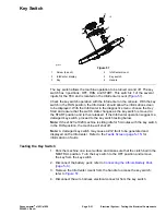
power and ground. The key switch needs to be in the RUN or START position
for the components on the network to be activated.
Two specially designed, twisted wires form the CAN bus. These wires provide
the data pathways between the components on the network. The ering term for
these cables are CAN High and CAN Low. The CAN bus wires are red/white
(CAN High) and black/white (CAN Low). At each end of the CAN bus is a 120
ohm termination resistor; refer to
CAN-bus Terminator Resistor (page 5–39)
.
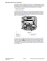
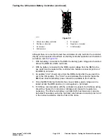
Testing the CAN bus
1. Park the machine on a level surface and make sure that the clutch bail in the
NEUTRAL position. Turn the key switch to the OFF position and remove
the key from the key switch.
2. Disconnect the battery pack; refer to
Connecting the Lithium Battery Pack
(page 5–3)
.
3. The Toro DIAG connector is located inside the upper cover assembly; refer
to
Electrical System: Testing the Electrical Components
Page 5–24
Greensmaster
®
e1021/e1026
20246SL Rev A
Содержание 04831
Страница 4: ...NOTES NOTES Page 4 Greensmaster e1021 e1026 20246SL Rev A ...
Страница 6: ...g340650 Figure 1 Model 04831 shown Preface Page 6 Greensmaster e1021 e1026 20246SL Rev A ...
Страница 14: ...Safety Safety and Instructional Decals Page 1 6 Greensmaster e1021 e1026 20246SL Rev A ...
Страница 46: ...Troubleshooting Battery Charger Error and Fault Codes Page 3 14 Greensmaster e1021 e1026 20246SL Rev A ...
Страница 136: ...Electrical System Service and Repairs Page 5 56 Greensmaster e1021 e1026 20246SL Rev A ...
Страница 162: ...Controls Wheels and Accessories Service and Repairs Page 6 26 Greensmaster e1021 e1026 20246SL Rev A ...
Страница 210: ...Universal Groomer Optional Service and Repairs Page 8 20 Greensmaster e1021 e1026 20246SL Rev A ...
Страница 213: ...Greensmaster e1021 e1026 Drawing 122 1647 Rev A Sheet 1 of 1 20246SL Rev A Page A 3 Electrical Schematic g361655 ...
Страница 214: ...Page A 4 20246SL Rev A Greensmaster e1021 e1026 Drawing 122 1734 Rev D Sheet 1 of 2 Wire Harness Drawing CV g361656 ...
Страница 215: ...Greensmaster e1021 e1026 Drawing 122 1734 Rev D Sheet 2 of 2 20246SL Rev A Page A 5 Wire Harness Drawing g361657 ...
Страница 216: ......


