


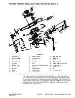
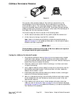


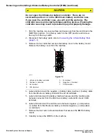
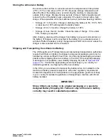
CAN-bus Terminator Resistor
g291761
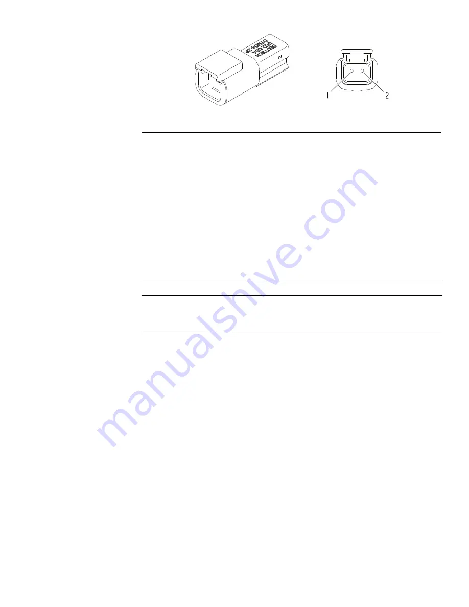
Figure 64
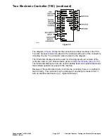
The system communication between the electrical components on the
Greensmaster e1021/e1026 machines are accomplished on a CAN-bus
communication system. The 2 specially designed, twisted cables form the
bus for the networks used on the e1021/e1026. These wires provide the data
pathways between the machine components. At the ends of the twisted pair of
bus cables are 120 ohm terminator resistors.
The resistors plug into the wire harness in the following areas:
1. On the main wire harness under the key switch, inside the handle cover.
2. On the main wire harness near the TEC controller.
Note:
Refer to the Electrical Schematic and Wire Harness Drawings in
Appendix A (page A–1)
for additional information on the terminator resistor
locations and wire connections.
IMPORTANT
The terminator resistors at the ends of the bus cables are required
for proper electrical system operation.
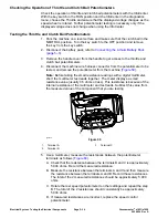
Testing the CAN-bus Terminator Resistor
1. The CAN-bus terminator resistor (
) can be tested using a digital
multimeter (ohms setting). Locate the CAN-bus terminator resistor and
remove the cable tie that secures the resistor to the wire harness. Unplug the
resistor from the wire harness for testing.
2. Check the resistor and resistor holder for damage or corrosion and clean
or repair if necessary.
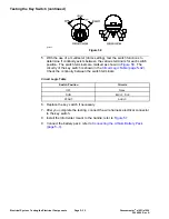
3. Use a digital multimeter (ohms setting) to measure the resistance value for
the CAN-bus terminator resistor. There should be 120 ohms resistance
between the terminals 1 and 2.
4. If the testing determines that the CAN-bus terminator resistor is damaged,
replace the CAN-bus terminator resistor.
5. After you complete the testing, ensure that the CAN-bus terminator resistor
is fully installed into the wire harness connector and secured to the wire
harness with cable tie.
6. If the resistor test correctly and a circuit problem still exists, check the
CAN-bus; refer to
Testing the CAN bus (page 5–24)
, wire harness drawings
in
Appendix A (page A–1)
for additional information, or contact an Authorized
Toro Distributor for assistance.
Greensmaster
®
e1021/e1026
Page 5–39
Electrical System: Testing the Electrical Components
20246SL Rev A
Содержание 04831
Страница 4: ...NOTES NOTES Page 4 Greensmaster e1021 e1026 20246SL Rev A ...
Страница 6: ...g340650 Figure 1 Model 04831 shown Preface Page 6 Greensmaster e1021 e1026 20246SL Rev A ...
Страница 14: ...Safety Safety and Instructional Decals Page 1 6 Greensmaster e1021 e1026 20246SL Rev A ...
Страница 46: ...Troubleshooting Battery Charger Error and Fault Codes Page 3 14 Greensmaster e1021 e1026 20246SL Rev A ...
Страница 136: ...Electrical System Service and Repairs Page 5 56 Greensmaster e1021 e1026 20246SL Rev A ...
Страница 162: ...Controls Wheels and Accessories Service and Repairs Page 6 26 Greensmaster e1021 e1026 20246SL Rev A ...
Страница 210: ...Universal Groomer Optional Service and Repairs Page 8 20 Greensmaster e1021 e1026 20246SL Rev A ...
Страница 213: ...Greensmaster e1021 e1026 Drawing 122 1647 Rev A Sheet 1 of 1 20246SL Rev A Page A 3 Electrical Schematic g361655 ...
Страница 214: ...Page A 4 20246SL Rev A Greensmaster e1021 e1026 Drawing 122 1734 Rev D Sheet 1 of 2 Wire Harness Drawing CV g361656 ...
Страница 215: ...Greensmaster e1021 e1026 Drawing 122 1734 Rev D Sheet 2 of 2 20246SL Rev A Page A 5 Wire Harness Drawing g361657 ...
Страница 216: ......


