

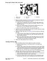
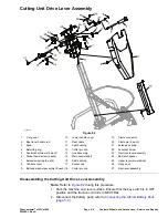

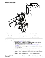


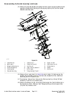


Disassembling the Cutting Unit Drive Lever Assembly (continued)
3. Remove the bolts and washers (9) that secures the controls covers (item 8
and 10) to the upper receiver weldment (25) and handle assembly.
4. Remove the reel lever handle rod (2) from the reel lever assembly (27).
5. If necessary, remove the reel lever knob (3) from the reel lever handle (2).
6. Remove the cotter pin (18) and clevis pin (20) that secures the link assembly
(14) to the main control shaft (15).
7. Remove the cotter pin (18) and clevis pin (20) that secures the clevis
connector (19) to the reel lever assembly (27).
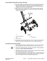
8. Remove the extension spring (21) from the reel lock lever (23).
9. Remove the flange nut (26) and shoulder screw (22) that secures the reel
lock lever (23) to the upper receiver weldment (25). Remove the reel lock
lever (23) and bail latch spacer (24).
10. Remove the retaining ring (4) and V-ring seal (1) that secures the reel lever
assembly (27) to the main control shaft (15). Slide and remove the reel
lever assembly.
11. Remove the socket head screws (6) and control shaft clamps (5) that secures
the main control shaft (15) to the upper receiver weldment (23).
12. Remove the main control shaft (15). If necessary, remove the split bushing
(16 and 12) from the main control shaft.
Assembling the Cutting Unit Drive Lever Assembly
1. If removed, apply a coat of grease in inner diameter of split bushings (item
16 and 12 in
) and install the split bushing onto the main control
shaft (15).
2. Position the main control shaft (15) on the upper receiver weldment (25)
and secure the main control shaft (15) with control shaft clamps (5) and
the bolts (6).
3. Slide the reel lever assembly (27) and V-ring seal (1) onto the main control
shaft (15) and secure reel lever assembly with the retaining ring (4).
4. Install the reel lock lever (23) and bail latch spacer (24) to the upper receiver
weldment (25) and secure with the shoulder screw (22) and flange nut (26).
5. Install the link assembly (14) to the main control shaft (15) with clevis pin
(20). Secure the clevis pin with the cotter pin clip (13).
6. Install the clevis connector (19) to the reel lever assembly (27) with clevis pin
(20) and secure the clevis pin with the cotter pin clip (18).
7. Install the reel lever handle rod (2) to the reel lever assembly (27).
8. If removed, install the reel lever knob (3) to reel lever handle rod (2).
9. Install the control covers (8 and 10) to the handle assembly with bolts and
washers (9).
10. Connect the battery pack; refer to
Connecting the Lithium Battery Pack
(page 5–3)
.
Controls, Wheels and Accessories : Service and Repairs
Page 6–10
Greensmaster
®
e1021/e1026
20246SL Rev A
Содержание 04831
Страница 4: ...NOTES NOTES Page 4 Greensmaster e1021 e1026 20246SL Rev A ...
Страница 6: ...g340650 Figure 1 Model 04831 shown Preface Page 6 Greensmaster e1021 e1026 20246SL Rev A ...
Страница 14: ...Safety Safety and Instructional Decals Page 1 6 Greensmaster e1021 e1026 20246SL Rev A ...
Страница 46: ...Troubleshooting Battery Charger Error and Fault Codes Page 3 14 Greensmaster e1021 e1026 20246SL Rev A ...
Страница 136: ...Electrical System Service and Repairs Page 5 56 Greensmaster e1021 e1026 20246SL Rev A ...
Страница 162: ...Controls Wheels and Accessories Service and Repairs Page 6 26 Greensmaster e1021 e1026 20246SL Rev A ...
Страница 210: ...Universal Groomer Optional Service and Repairs Page 8 20 Greensmaster e1021 e1026 20246SL Rev A ...
Страница 213: ...Greensmaster e1021 e1026 Drawing 122 1647 Rev A Sheet 1 of 1 20246SL Rev A Page A 3 Electrical Schematic g361655 ...
Страница 214: ...Page A 4 20246SL Rev A Greensmaster e1021 e1026 Drawing 122 1734 Rev D Sheet 1 of 2 Wire Harness Drawing CV g361656 ...
Страница 215: ...Greensmaster e1021 e1026 Drawing 122 1734 Rev D Sheet 2 of 2 20246SL Rev A Page A 5 Wire Harness Drawing g361657 ...
Страница 216: ......


