Form No. 3445-180 Rev A
Z Master
®
Professional 7500-D
Series Riding Mower
With 144in TURBO FORCE
Rear Discharge
Mower
Model No. 72144—Serial No. 400000000 and Up
Register at www.Toro.com.Original Instructions (EN)
*3445-180*
Страница 1: ...3445 180 Rev A Z Master Professional 7500 D Series Riding Mower With 144in TURBO FORCE Rear Discharge Mower Model No 72144 Serial No 400000000 and Up Register at www Toro com Original Instructions EN...
Страница 2: ...cause exposure to chemicals known to the State of California to cause cancer birth defects or other reproductive harm Introduction This rotary blade riding lawn mower is intended to be used by profes...
Страница 3: ...ger Warning or Caution Danger indicates an imminently hazardous situation which if not avoided will result in death or serious injury Warning indicates a potentially hazardous situation which if not a...
Страница 4: ...Cleaner 45 Servicing the Engine Oil 46 Inspecting the Engine Valve Clearance 47 Fuel System Maintenance 48 Draining the Fuel Filter Water Separator 48 Replacing the Water Separator 49 Checking the Fu...
Страница 5: ...ined familiar with the instructions and physically capable to operate or service the machine Always keep the roll bar in the fully raised and locked position and use the seat belt Do not operate the m...
Страница 6: ...ees Use the slope chart to determine the degree of slope of hills before operating Do not operate this machine on a slope greater than 15 degrees Fold along the appropriate line to match the recommend...
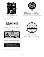
Страница 7: ...ar eye protection 9 Flush eyes immediately with water and get medical help fast 5 Read the Operator s Manual 10 Contains lead do not discard decaloemmarkt Manufacturer s Mark 1 Indicates the blade is...
Страница 8: ...place decal116 8283 116 8283 1 Warning read the Operator s Manual for instructions on torquing the blade bolt nut to 75 to 81 N m 55 to 60 ft lb decal133 8062 133 8062 decal117 3276 117 3276 1 Engine...
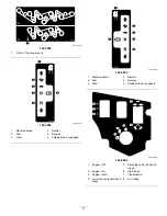
Страница 9: ...d wear hearing protection 4 Runover backover hazard do not carry passengers look behind you when mowing in reverse 2 Cutting dismemberment hazard of the hand mower blade entanglement hazard of the han...
Страница 10: ...d the instructions before servicing or performing maintenance 2 Warning lock the deck wings and read the instructions before servicing or performing maintenance decal135 0679 135 0679 1 Rotating drive...
Страница 11: ...everse 3 Slow 6 Parking brake engaged decal142 3953 142 3953 1 Machine speed 4 Neutral 2 Fast 5 Reverse 3 Slow 6 Parking brake engaged decal142 3956 142 3956 1 Engine Off 5 Raise the center deck and w...
Страница 12: ...ual for further instructions 12 Grease the front caster pivots refer to the Operator s Manual for further instructions 5 locations 5 Check the tire pressure 2 locations 13 96 and 144 inch Models 6 Che...
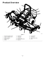
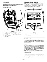
Страница 13: ...ht of cut pin 6 Audible alarm 11 Anti scalp roller 2 Wing deck height of cut pin 7 Fuel gauge 12 Center deck 3 Motion control lever 8 Fuel tank cap 13 Machine caster wheel 4 Display monitor 9 Wing dec...
Страница 14: ...izon Display Monitor 1 Screen 3 Buttons 2 LED status light Information Screen The information screen displays information relative to machine operation refer to the Software Guide for more information...
Страница 15: ...pears and the engine cranks when turned to the START position Note The system allows you to start the machine the with the PTO switch engaged but does not engage the blades You must reset the PTO to e...
Страница 16: ...all length 257 3 cm 101 5 16 inches Roll bar up 182 4 cm 71 13 16 inches Overall height Roll bar down 129 5 cm 51 inches Drive wheels 131 cm 51 1 2 inches Tread width center to center of tires widthwi...
Страница 17: ...rts when necessary Fuel Safety Fuel is extremely flammable and highly explosive A fire or explosion from fuel can burn you and others and can damage property To prevent a static charge from igniting t...
Страница 18: ...iodiesel portion of the fuel meet specification ASTM D6751 or EN14214 The blended fuel composition should meet ASTM D975 or EN590 Painted surfaces may be damaged by biodiesel blends Use B5 biodiesel c...
Страница 19: ...pressure to the upper part of the roll bar 2 Pull both knobs out and rotate them 90 degrees so they are not engaged Figure 10 3 Lower the roll bar to the down position Figure 10 g225804 Figure 10 1 Up...
Страница 20: ...angle view to assist with blind spots Adjust the left and right mirror to ensure that you have an optimal viewing angle Using the Motion Control Levers g004532 Figure 12 1 Motion control levers NEUTRA...
Страница 21: ...n rough terrain the seat has a half second delay before the engine begins to shutdown Checking the Normal Engine Starting Chart System Motion Control Levers Parking Brake PTO Operator Outcome Both Lev...
Страница 22: ...state of system item that is in bold text is being checked in each scenario System Motion Control Levers Parking Brake PTO Blades Operator Outcome Both levers moved in or right or left lever moved in...
Страница 23: ...left lever moved in Parking Brake Disengaged Disengaged Raise off the seat but do not get off Engine must begin shutdown within 1 second Running idle 1 3 throttle or efficient mode Both Levers Out Pa...
Страница 24: ...e or efficient mode Both levers moved in or right or left lever moved in Parking Brake Disengaged Engaged and Deck wings up Operator in the seat PTO must begin shutdown within 1 second engine stays ru...
Страница 25: ...to unlock the seat Figure 13 g019754 Figure 13 Unlatching the Seat g019755 Figure 14 1 Seat latch 2 Seat Changing the Seat Suspension The seat is adjustable to provide a smooth and comfortable ride Po...
Страница 26: ...wing Park the machine on a level surface Disengage the power takeoff and lower the attachments Engage the parking brake Shut off the engine and remove the key Wait for all moving parts to stop Operate...
Страница 27: ...machine Use an angle indicator to determine the approximate slope angle of the area Never operate on slopes greater than 15 Evaluate the site conditions of the day to determine if the slope is safe f...
Страница 28: ...rop offs or water 5 Keep a safe distance twice the width of the machine between the machine and any hazard 3 Water Lowering the Wing Decks Important You must unfold the wing decks before you can engag...
Страница 29: ...ter deck Operating the Mower Blade Control Switch PTO The blade control switch PTO starts and stops the mower blades and any powered attachments Engaging the Blade Control Switch PTO Note Engaging the...
Страница 30: ...the engine the first time after adding fuel to an empty fuel system g363138 Figure 22 Shutting Off the Engine CAUTION Children or bystanders may be injured if they move or attempt to operate the mach...
Страница 31: ...deck control switch the center deck will raise first then the wing decks 4 Shut off the engine remove the key and wait for all moving parts to stop before leaving the operating position 5 Remove the...
Страница 32: ...machine can spin very rapidly You may lose control of the machine and cause personal injury or damage to the machine Use caution when making turns Slow the machine down before making sharp turns Drivi...
Страница 33: ...place B Unlock the cam locks located on the height of cut channel on the wing deck Figure 28 g239055 Figure 28 1 Cam lock 3 Lynch pin 2 Height of cut pin C Remove the lynch pin from the height of cut...
Страница 34: ...cut adjust the anti scalp rollers by removing the mounting hardware Figure 30 g018862 Figure 30 1 Locknut 3 8 inch 3 Spacer 2 Anti scalp rollers 4 Bolt 5 Place the rollers in 1 of the positions shown...
Страница 35: ...Alternate the mowing direction to keep the grass standing straight This also helps disperse clippings which enhances decomposition and fertilization Mowing at Correct Intervals Grass grows at differen...
Страница 36: ...e fuel and remove the key before storing or transporting the machine Using the Drive Train Brake Release The drive train brake releases are located on each of the wheel motor gearboxes Releasing the d...
Страница 37: ...nt Do not tighten the set screws beyond this point otherwise damage may occur 3 Using a 1 8 inch Allen wrench to hold the set screws tighten the sealing nuts using a 7 16 inch wrench to the manifold b...
Страница 38: ...ramps for each side of the machine Do not exceed a 15 degree angle between the ramp and the ground or between the ramp and the trailer or truck Ensure that the length of the ramp is at least 4 times...
Страница 39: ...machine up the ramp 2 Drive the machine forward down the ramp 5 Shut off the engine remove the key and engage the parking brake 6 Tie down the machine near the front caster wheels and the rear frame w...
Страница 40: ...Disconnect the cable from the negative terminal of the battery before repairing the machine To ensure optimum performance use only genuine Toro replacement parts and accessories Replacement parts and...
Страница 41: ...bushings Every 500 hours Check the wheel lug nuts Adjust the caster pivot bearing Every 800 hours Inspect the engine valve clearance Change the drive wheel gearbox oil Change the hydraulic fluid and f...
Страница 42: ...moving parts to stop before leaving the operating position 3 Clean the grease fittings with a rag Note Make sure that you scrape any paint off the front of the fitting s 4 Connect a grease gun to the...
Страница 43: ...Wipe up any excess grease g250852 Figure 38 Greasing the Caster Pivots Service Interval Every 400 hours Yearly whichever comes first more often in dirty or dusty conditions Yearly Repack the caster wh...
Страница 44: ...rd Note Do not thread the spacer nut all of the way onto the end of the axle Leave approximately 3 mm 1 8 inch from the outer surface of the spacer nut to the end of the axle inside the nut 12 Insert...
Страница 45: ...cause an air leak Replace a damaged air cleaner body 4 Check the air intake system for leaks damage or loose hose clamps 5 Service the air cleaner filter and safety element when alerted Figure 40 Imp...
Страница 46: ...vice category DH 2 Important Using engine oil other than API classification CJ 4 or higher ACEA E6 or JASO DH 2 may cause the diesel particulate filter to plug or cause engine damage Use the following...
Страница 47: ...ate the machine less than 200 hours change the engine oil and filter If possible run the engine just before changing the oil because warm oil flows better and carries more contaminants than cold oil 1...
Страница 48: ...e disengage the blade control switch and engage the parking brake 2 Shut off the engine remove the key and wait for all moving parts to stop before leaving the operating position 3 Place a drain pan b...
Страница 49: ...eparator more often in dirty and dusty conditions g031412 Figure 46 The engine has 2 fuel filters as shown in Figure 47 g233831 Figure 47 1 Filter locations Checking the Fuel Lines and Connections Ser...
Страница 50: ...rformance and life charge the battery in storage when the open circuit voltage drops to 12 4 V Note To prevent damage due to freezing fully charge the battery before putting it away for winter storage...
Страница 51: ...at anytime during the jump starting procedure Do not attempt to jump start with loose or corroded battery terminals otherwise damage may occur to the engine DANGER Jump starting a weak battery that is...
Страница 52: ...ter battery 6 Make the final connection on the engine block of the stalled machine not to the negative post away from the battery Stand away from the machine 7 Start the vehicle and remove the cables...
Страница 53: ...es as needed If the machine tracks to the right loosen the bolts and adjust the left stop plate rearward on the left T slot until the machine tracks straight Figure 51 If the machine tracks to the lef...
Страница 54: ...g the machine g001055 Figure 54 Checking the Wheel Lug Nuts Service Interval After the first 100 hours Check the wheel lug nuts Every 500 hours Check the wheel lug nuts Torque the wheel lug nuts to 12...
Страница 55: ...Interval After the first 200 hours Every 400 hours If the oil becomes contaminated contact your Toro Distributor because the system must be flushed Contaminated oil looks milky or black when compared...
Страница 56: ...t on the opposite side Important Do not overfill the gearbox overfilling the gearbox may damage it Changing the Drive Wheel Gearbox Oil Service Interval After the first 50 hours Every 800 hours 1 Park...
Страница 57: ...side of the tank g227787 Figure 58 1 Expansion tank cap 3 Add line 2 Full line 5 If coolant level is low remove the expansion tank cap and add the specified coolant Figure 58 Important Do not overfil...
Страница 58: ...the radiator 6 Remove the coolant hose from the oil cooler and drain the coolant from the engine block Figure 59 g233651 Figure 59 1 Coolant hose 7 Install the drain plugs and hoses 8 Fill radiator w...
Страница 59: ...g a ratchet in the square hole in the idler arm rotate the idler arm rearward to remove tension on the idler spring Figure 61 8 Remove the belt from the mower deck pulleys Figure 61 g243945 Figure 61...
Страница 60: ...belt covers and floorboard Checking the Alternator Belt Tension Service Interval Every 100 hours 1 Apply 44 N 10 lb of force to the alternator belt midway between the pulleys 2 If the deflection is n...
Страница 61: ...h other refer to Adjusting the Motion Control Linkage page 61 6 Repeat to adjust the control levers Adjusting the Motion Control Linkage Located on either side of the machine below the seat are the pu...
Страница 62: ...rotating the double nuts on the rod in the appropriate direction until the wheels slightly creep in reverse Figure 66 g228557 Figure 66 1 Turn here to adjust 2 Loosen here right hand thread 11 Move t...
Страница 63: ...Alternate fluids If the Toro fluid is not available Mobil 424 hydraulic fluid may be used Note Toro does not assume responsibility for damage caused by improper substitutions Note Many hydraulic flui...
Страница 64: ...ngage the PTO move the motion control levers to the NEUTRAL LOCK position and engage the parking brake 2 Move the throttle lever to the SLOW position shut off the engine remove the key and wait for al...
Страница 65: ...weld them On multi bladed machines take care as rotating one blade can cause other blades to rotate Replace worn or damaged blades and bolts in sets to preserve balance Servicing the Cutting Blades To...
Страница 66: ...ting edge of the blades at the same position as in step 4 Note The difference between the dimensions obtained in steps 4 and 5 must not exceed 3 mm 1 8 inch Note If this dimension exceeds 3 mm 1 8 inc...
Страница 67: ...blade assembly into the spindle shaft Figure 77 g298850 Figure 77 1 Top spindle nut 3 Blade bolt 2 Flat of the spindle shaft 3 Apply copper based lubricant or grease to the threads of the blade bolt...
Страница 68: ...lowers and both wings are completely unfolded to the cutting height 9 Shut off the engine remove the key and wait for all moving parts to stop before leaving the operating position 10 Measure from the...
Страница 69: ...point adjustment to gain more adjustment Note Loosen or tighten the single point adjustment bolt enough to move the height of cut plate mounting bolts at least 1 3 the length of the available travel i...
Страница 70: ...ening the left and right rear adjustments Figure 82 until all 4 blades have a minimum of 1 5 mm 1 16 inch rake Adjust the rear wing wheels so that they lightly touch the ground with minimal pressure T...
Страница 71: ...e clevis pins and hairpin cotters from each wing deck Remove the height of cut pin from the deck lift plate on the right side of the center deck 9 Lower the wing decks but do not draw them into the op...
Страница 72: ...ower deck pin assemblies and bolts into the lower deck pivot points and hand tighten 23 To ease installing the wing deck sections carefully remove the exposed end of the spring that applies pressure t...
Страница 73: ...ease or oil around the engine and exhaust area Cleaning the Machine and Mower Deck Service Interval Before each use or daily 1 Park the machine on a level surface disengage the blade control switch PT...
Страница 74: ...47 6 Check the tire pressure refer to Checking the Tire Pressure page 54 7 Change the hydraulic fluid and filter refer to Checking the Tire Pressure page 54 8 Charge the battery refer to Charging the...
Страница 75: ...connections for good contact Clean the connector terminals thoroughly with electrical contact cleaner apply dielectric grease and connect The engine does not start starts hard or fails to keep runnin...
Страница 76: ...r The machine vibrates abnormally 7 The motor mount is loose or worn 7 Contact an Authorized Service Dealer 1 The blade s is not sharp 1 Sharpen the blade s 2 A cutting blade s is are bent 2 Install a...
Страница 77: ...ENGINE COOLANT TEMP SENSOR INTAKE MANIFOLD TEMP SENSOR INTAKE THROTTLE VALVE EGR PRESSURE K CONNECTOR 94 PIN LIFT LOWER SWITCH GROUND SPEED RANGE BLACK P02 12 GREEN P03 12 GRAY P01 10 RH DECK POSITION...
Страница 78: ...RANGE ORANGE GRAY RED BLACK RED GREEN RED WHITE BLACK BLACK RED GREEN BLUE BLACK BLUE BLACK ORANGE RED ORANGE RED RED GREEN SEN01 TRANS TEMP SENSOR P05 1 P05 2 S1 P09 2 P09 1 L04 S2 P08 2 P08 1 CLUTCH...
Страница 79: ...SI OIL COOLER 1 0 691 1 1 1 1 025 1 1 025 PORT 2 0 031 in IMPLEMENT RELIEF 4000 PSI 4000 PSI FLUSH VALVE FLUSH VALVE Port A FWD Port B REV Port C FWD Port D REV T P A B 11 96 1 L 1 83 1 095 CID L1 X1...
Страница 80: ...to restaurants grocery stores hotels schools and hospitals and on a wide variety of products Additionally some online and mail order retailers provide Prop 65 warnings on their websites or in catalogs...