GTM1 User manual V-2020-08-12
7 |
E N
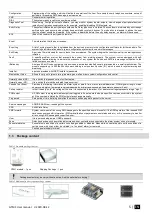
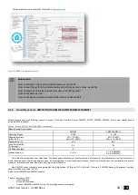
Figure 4 General view of the module
1.5
Meaning of LEDs and contacts
Table 3 Meaning of LEDs
Name
Indication variations
Meaning
PWR (green) built-in
LED
Watchdog heart beat blinking, remains lit for
50ms, and turns off after 1000ms.
The module is functioning.
Off
The module is out of order or no voltage
REG (yellow) built-in
LED
Lights continuously
Modem has been registered to the network
Flashes, remains lit for 50ms, turns off for
300ms
Modem is being registered to the GSM network.
Blinking fast, remains lit for 50ms turns off
for 50ms
PIN code of SIM card error. PIN code request should be removed
Off
Modem failed to register to the network.
DATA (red) built-in LED
Lights continuously
The memory of the module contains unsent reports to the user or to the
server.
Off
All reports has been send.
FN (blue) built-in LED
ON
OFF
Selected output or input ON
Selected output or input OFF
Table 4 Terminal block. Contacts.
N
a
m
e
Optional functions and Description
AC/DC
DC
10-30V
AC
12-24V
Max
0.2A
OUT1
OUT2
Outputs
1A
AUX+
10-30V, 1A
I/O1-I/O2
Programmable functions
Input with 10K resistor to the VD+ (Pull UP
Output 1A
Analog voltage input 0-30V
Max available voltage
30V
IO3/ D0
Programmable functions
0-30V analog input (zone or sensor)
Output
2-wire smoke detector (fire current loop)
0-20mA, 4-20mA current loop sensor
Max available voltage
30V
IN1/D1
Programmable functions
0-30V input
Input with 10K resistor to the VD+ (Pull UP)
The zone for security system NC/NO/EOL/EOL+Tamper
Wiegand (1) interface, RFID reader, keypad
Max available voltage
30V
COM
Negative supply terminal for keyboard(s), indicators and sensors.


