GTM1 User manual V-2020-08-12
37 |
E N
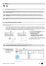
Outputs can be set as timers.
1.
When output is activated for “Out
Timer” time interval,
2.
Relay contact start changing state
from ON (pulse time ON) to OFF
(Pulse time Off)
3.
This cycle will repeat until output is
deactivated.
Output signal
Pulse time ON
Pulse time OFF
Pulse time ON
Pulse time OFF
Output state
Output ON
Output OFF
Bell:
Output for connection of audible sounder (siren). After the alarm
system actuation a continuous or pulse (fire) signal is generated.
OFF
ON
Alarm
Bell time
Bell
ARM/DISARM:
Output for connection of light indicator of the alarm
system status. When the alarm system is on a continuous signal is
generated.
OFF
ON
ARM/DISARM
Open
Close
Open
ARM
DISARM
Buzzer:
Output for connection of audio indicator. After the alarm system
activated a pulse signal is generated within Exit Delay time, and continuous
signal - within Entry Delay time or when the alarm system is disturbed.
When the alarm system is turned off, operates like keyboard buzzer.
OFF
ON
Open
Command - ARM
Exit Delay
Close
Entry Delay
Command - DISARM
Buzzer
Flash:
Output for connection of light indicator. When the alarm system
is on, a continuous signals generated, and if the alarm system is
disturbed - pulse signal. Signal is terminated by turning off the alarm
system.
OFF
ON
Flash
Open
Command - ARM
Close
Alarm
Open
Remote Control:
Output designed for connection of electrical devices
which will be controlled by SMS message or phone call a) control by SMS
message
SMS
OFF
ON
Remote Control
Pulse
OFF
ON
Remote Control
Level
SMS 1
SMS 2
Remote Control
b) control by phone call
OFF
ON
Remote Control
Pulse
Dial
OFF
ON
Remote Control
Level
Dial 1
Dial 2
System State:
Output for connection of light indicator of the alarm system
status. Within Exit Delay time a pulse signal is generated, and when the
alarm system activated
– continuous. Signal is terminated by turning off the
alarm system.
OFF
ON
System State
Open
Exit Delay
Close
Open
AC OK:
Output for connection of indicator about control panel supply
from alternating current
OFF
ON
AC OK
AC OK
AC Lost
AC OK
Ready:
Output for connection of light indicator of input statuses. If all zones
are clear (none violated), a continuous signal is generated.
OFF
ON
Ready
Zone Fault
Zone OK
Battery OK:
Output for connection of indicator about control panel supply
from battery.
OFF
ON
Battery OK
Battery OK
Battery Lost
Battery OK
Alarm indication:
Output for connection of light indicator showing alarm
status of the alarm system. After the alarm system actuation a continuous
signal is generated.
Lost Primary Channel:
Output where a continuous signal is generated
when communication with primary channel was lost.
OFF
ON
Lost Primary
Channel
Lost Primary Channel
Restore Primary Channel


