GTM1 User manual V-2020-08-12
16 |
E N
4.2
Inputs
IO1and IO2 programmable selectable input or output
-
IO1: 0-30V
-
IO2: 0-30V
IO3/D0 programmable selectable
-
IO3/D0: 0-30V analog input (zone or sensor)
-
Output
-
IO3/D0: 0-20mA 4-20mA current loop sensor
-
2- wire Smoke Detector (Fire urrent loop)
IN1/D1: 0-30V
1W programmable selectable
-
Digital input (Max 3.3V!!!)
-
Dallas 1-wire bus
-
Aosong 1-wire bus
Wiegand keypad
inputs: IO3/ D0 ir IN1/D1
4.2.1
4-20mA sensors
PREPARE the module GTM1
-
Insert SIM card
-
Screw GSM antenna
-
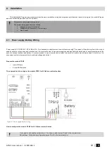
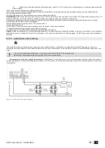
Connect analog current sensor as in the diagram
-
Connect the power supply
-
Connect the module to the computer via mini USB
-
Install SERA2 software.
•
website
•
(HELP & SUPPORT> Downloads)
•
Open SERA2
-
Go to
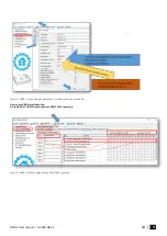
SERA2> System Options> General System Options
-
Set I/O3 Settings > 0-20mA, 4-20mA Current Loop Sensor
-
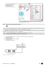
Press
“Write”
icon (in the command line)
Figure 25 Example of 4-20mA sensor wiring
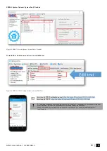
If you want to edit existing configuration,
You have to read it (press “Read” in the command line)
Edit settings,
Write edited configuration (press “Write” in the command line)


