GTM1 User manual V-2020-08-12
35 |
E N
4.7
Outputs
The output toggles to its set up state when a specific event has occurred in the system. The output can be used to open/ close garage doors,
activate lights, heating, watering and much more.
Each output has a name that can be customized by the user.
Typically, the name specifies a device type connected to a determined
output, for Example
:
Lights
If the output is not in used, it must be disabled.
Once the output is disabled, it can no longer be turned ON or OFF unless it is
enabled again.
It is possible to instantly turn ON an individual output for a determined time period and automatically turn it OFF when the time period
expires.
4.7.1
Output PGM wiring. Bell, Relay, Led Wiring
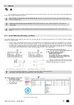
Output switch to ground when activated from the module. Connect the positive side of the device to be activated to the VD+ terminal. Connect the negative
terminal to the selected output.
1.
Connect devices to the selected outputs as shown in the figures below. For sound signaling we recommend to use siren DC 12V up to 1500mA.
It is recommended to connect the siren to the system by using 2 x 0,75 sq. mm double insulation cable. Auxiliary BUZZER is recommended to
be installed inside the premises not far from the entrance. Buzzer operates together with the main siren also when the system starts calculating
the time to leave the premises and the time till alarm response of the security system after entering the premises (see claus e 7.1). It is possible
to use buzzer of hit point PB12N23P12Q or similar modified piezoelectric 12V DC, 150mA max Buzzer.
Output mode: timer, steady, pulse count
.
The output action can
automatically switch ON
or OFF under the following conditions:
-
System armed or disarmed, -
-
Alarm begins or stops, -
-
Temperature falls below the set MIN value,
-
Temperature rises above the set MAX value,
-
Zone violated, Zone restored.
The user can also set a custom text, which will be
sent by SMS text message to user phone number when the
automatic PGM output action is carried out.
If you want to edit existing configuration,
You have to read it (press “Read” in the command line)
Edit settings,
Write edited configuration (press “Write” in the command line)
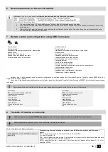
Set output’s parameters step by step:
1.
Go to SERA2 > Outputs
2.
Enter the required parameters.
3.
If the output is not in used, it
should be disabled
4.
Press “Write” icon.
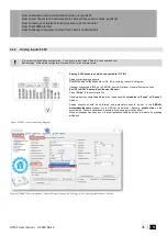
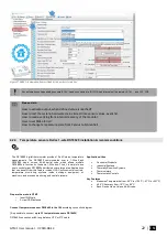
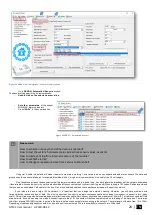
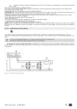
Figure 70Outputs (PGM) window
Figure 68 Bell, buzzer connection to I/O1, I/O2
Figure 69 Relay connection to , I/O1, I/O2

