


41
K-Cube Piezo Driver
4) Click the upp er Jog arrow on the GUI pan el to jog the piezo. Notice that the
position display increments 0.1V every time the button is clicked.
5) Click the low er Jog arrow on th e GUI pane l. Notice that the position display
decrements 0.1V every time the button is clicked.
5.4.5 Using the Controller as a Piezo Amplifier
Certain applications may require the piezo to be driven by a voltage generated from
an external source (e.g. a signal generator). The piezo K-Cube is designed to accept
an external 0 to 10V signal and handle the amplification from 10V to 75 or 150V.
As an example, the following procedure explains how to configure the unit as a piezo
amplifier.
1) Connect a 0 - 10V external source to the EXT IN connector on the rear panel.
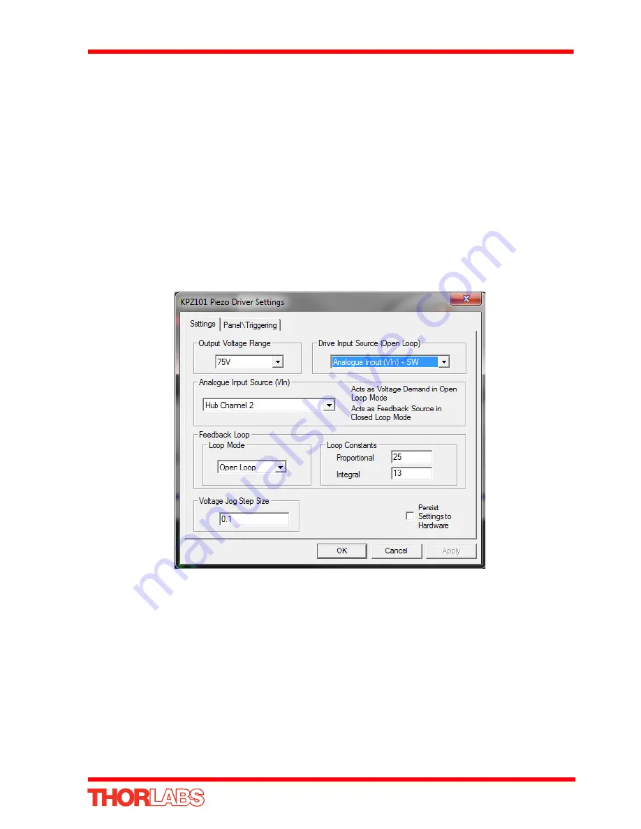
2) In the GUI panel, click the ‘Settings button to display the settings panel.
Fig. 5.7 Piezo settings panel
3) In the ‘Drive Input Source (Open Loop)’ field, select
Analogue Input (VIn) + SW
.
4) In the ‘Analogue Input Source (Ext In)’ field, select SMA Input.
5) In the ‘Feedback Loop’ field, select ‘Open Loop’.
6) Click ‘OK’ to save the settings and close the window.
Any voltage on the rear panel SMA conn ector is now amplified by th e unit and
presented at the HV OUT (pie zo drive) connector and the po sition of th e piezo
actuator can be controlled by varying the 0-10V external source.
If required, the contribution of the potentiometer can also be added by selecting the
appropriate option in the ‘Drive Input Source (open Loop)’ field. In this way it is


