Fuel System (Rev 1/97)
89
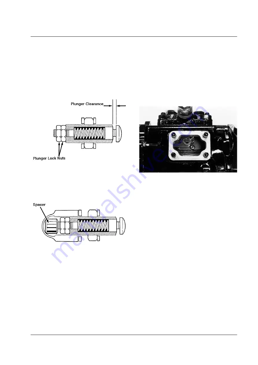
3. Check the plunger clearance with a feeler gauge. The
plunger clearance should be .016 in. (0.40 mm). Use
the two plunger lock screws to adjust the plunger clear-
ance if necessary.
Check Plunger Clearance
Adjust Fuel Limit Screw
1. The plunger must be locked in place so it will not move
while the fuel limit screw is being adjusted.
Lock Plunger
a.
Make a spacer 3/8 in. (9.5 mm) in diameter and 5/
16 in. (7.9 mm) long from a rod or a bolt.
b. Place the spacer in the cap nut.
c.
Screw the cap nut onto the fuel limit screw assem-
bly until it is finger tight.
d. Check the plunger and make sure it cannot move.
aea338
aea339
2. Place the fuel limit screw assembly in the governor
housing. Make sure the lock nut is turned out toward
the cap nut enough to allow adjustment.
3. Remove the inspection plate from the side of the injec-
tion pump housing.
Remove Inspection Plate
4. Remove the 20 wire from the reset switch so the reset
switch will not trip.
5. Disconnect the 8S circuit to the starter solenoid at the
jumper plug near the starter.
6. Turn the unit on, but do not start it.
7. Set the thermostat well below the box temperature so it
calls for high speed, and make sure that the throttle
lever is in the high speed position.
8. Use a screwdriver to push the fuel control rack toward
the front of the engine, approximately .25 in. (6 mm),
until the start spring is fully compressed. The start
spring is fully compressed when the governor lever
contacts the tensioner lever; you will feel a definite stop
when this happens. The start spring is a light spring that
is located between the tension lever and the governor
lever.
aea340


