Inspection and Reconditioning (Rev 1/97)
49
3. Measure the inside diameter of the connecting rod bear-
ings. If any of the connecting rod bearings are larger
than the wear limits (refer to Specifications) or show
significant damage, replace the entire set of connecting
rod bearing inserts.
4. Check each connecting rod bearing bore by installing
the rod caps with the rod bearing inserts removed and
properly torquing the rod cap bolts (refer to Specifica-
tions).
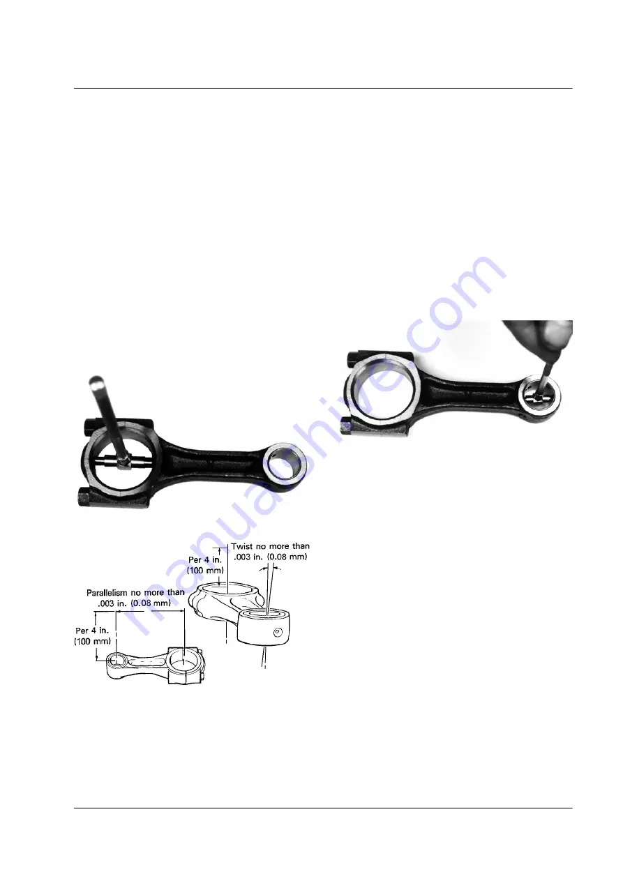
5. Measure each connecting rod bearing bore both parallel
and perpendicular to the rod. If the rod bearing bore is
more than .001 in. (0.25 mm) out of round the rod must
be reconditioned or replaced.
Measuring Rod Bearing Bore
Measuring Connecting Rod Twist and Parallelism
aea249
aea248
6. Use a connecting rod alignment fixture to check each
rod for twist and parallelism. The service limit for both
twist and parallelism is .003 in. per 4 in. (0.08 mm per
100 mm). If the twist or parallelism exceeds the wear
limit, straighten or replace the rod.
7. Measure the inside diameter of the connecting rod
bushings. If the connecting rod bushings are larger than
the wear limits (refer to Specifications) or show signifi-
cant damage, replace the connecting rod bushings.
Measuring Rod Bushing
8. To replace a connecting rod bushing, press the old
bushing out of the connecting rod. Press the new bush-
ing into the rod and make sure to align the oil hole in
the bushing with the oil hole in the top of the rod.
9. Finish the new bushing by reaming or honing it to size.
Each connecting rod bushing must be sized to its indi-
vidual wrist pin. Measure the outside diameter of the
wrist pin. Adding the suggested oil clearance of .0010-
.0019 in. (0.025-0.047 mm) to the outside diameter of
the wrist pin results in the correct inside diameter for
the finished connecting rod bushing.
aea250


