background image

User Manual

User Manual

R E S - 11 X R 3

R E S - 11 X R 3

Installation

Manual

Installation

Manual

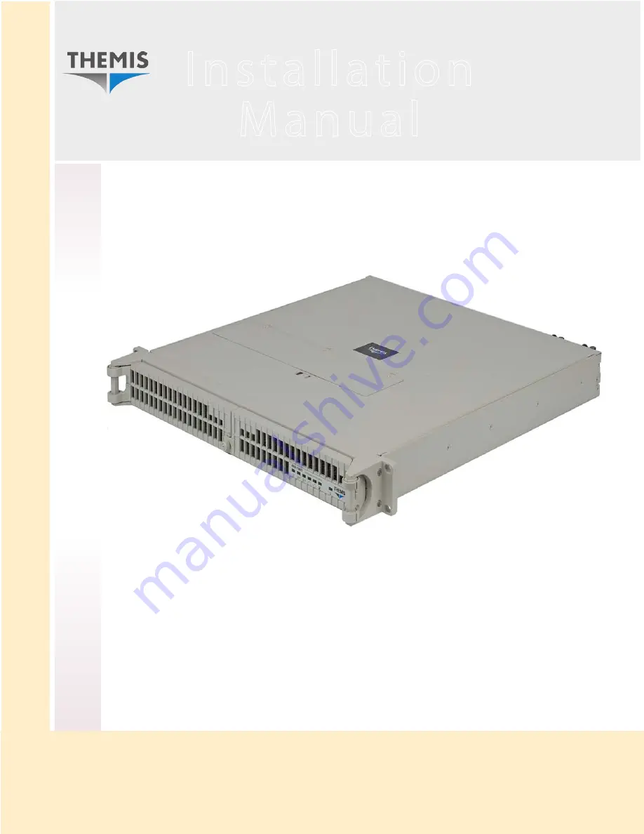
1 R U   1 9 ”   R a c k - M o u n t   R u g g e d   E n t e r p r i s e   S e r v e r

w i t h   X 8 S Ti   M o t h e r b o a r d   C o n f i g u r a t i o n

/ O n e   Q u a d - C o r e   5 5 0 0   o r   Q u a d / S i x - C o r e   5 6 0 0   X e o n   C P U

Содержание RES-11XR3

Страница 1: ...nual User Manual RES 11XR3 RES 11XR3 Installation Manual Installation Manual 1RU 19 Rack Mount Rugged Enterprise Server with X8STi Motherboard Configuration One Quad Core 5500 or Quad Six Core 5600 Xe...

Страница 2: ...u a d D u a l C o r e 5 5 0 0 o r Q u a d S i x C o r e 5 6 0 0 C P U R E S 11 X R 3 R E S 11 X R 3 O n e X e o n Q u a d D u a l C o r e 5 5 0 0 o r Q u a d S i x C o r e 5 6 0 0 C P U R E S 11 X R 3...

Страница 3: ...14 77 80 Fax 33 476 14 77 89 Themis Computer Americas and Pacific Rim 47200 Bayside Parkway Fremont CA 94538 Phone 510 252 0870 Fax 510 490 5529 World Wide Web http www themis com RES 11XR3 Installati...

Страница 4: ...mis Computer Inc Intel and Xeon are registered trademarks of Intel Corporation Red Hat is a registered trademark of Red Hat Inc Linux is a registered trademark of Linus Torvalds SuperMicro is a regist...

Страница 5: ...iii Themis Computer RES 11XR3 Installation Manual VersionRevisionHistory Version 1 0 July 2010...

Страница 6: ...ected from the power source Therefore the power cord and its connectors must always remain easily accessible Do not set up the device in the proximity of heat sources or in a damp location Make sure t...

Страница 7: ...ns 21 CFR 1040 for the USA and Canadian Radiation Emitting Devices Act REDR C 1370 Electrostatic Discharge ESD A sudden discharge of electrostatic electricity can destroy static sensitive devices or m...

Страница 8: ...Keep the work area free of non conductive materials such as ordinary plastic as sembly aids and Styrofoam 7 Use field service tools such as cutters screwdrivers and vacuums that are con ductive 8 Alw...

Страница 9: ...1 3 2 Onboard Voltage Monitoring 1 8 1 3 3 Fan Status Monitor with Software 1 8 1 3 4 CPU Overheat LED and Control 1 8 1 4 Power Configuration Settings 1 8 1 4 1 Slow Blinking LED for Suspend State I...

Страница 10: ...2 Installing a Lithium Battery 2 14 2 1 5 SAS SATA Storage Drive 2 14 2 1 5 1 Opening the RES 11XR3 Front Doors 2 14 2 1 5 2 Disk Drive Removal 2 15 2 1 5 3 Disk Drive Installation 2 17 2 1 6 Hot Swa...

Страница 11: ...Watch Dog Function 3 6 3 2 1 9 Power Button Function 3 6 3 2 1 10 Restore on AC Power Loss 3 6 3 2 1 11 Interrupt 19 Capture 3 6 3 2 2 Processor and Clock Options 3 7 3 2 2 1 CPU Ratio 3 7 3 2 2 2 Clo...

Страница 12: ...Mode 3 11 3 2 3 7 Demand Scrubbing 3 11 3 2 3 8 Patrol Scrubbing 3 11 3 2 3 9 Throttling Closed Loop 3 12 3 2 4 Intel VT d 3 12 3 2 5 SR 1OV Support 3 12 3 2 6 Intel I OAT 3 12 3 2 7 Active State Pow...

Страница 13: ...Onboard LAN2 Option ROM Load Onboard LAN3 Option ROM Load Onboard LAN4 Option ROM X8STi LN4 Only 3 18 3 3 6 10 Load SAS Option ROM X8STi 3F Only 3 18 3 3 6 11 Boot Graphics Adapter Priority 3 18 3 3 7...

Страница 14: ...Event Log 3 28 3 3 14 4 PCIE Event Log 3 28 3 3 14 5 Memory ECC Error Log 3 28 3 4 Security Settings 3 28 3 4 1 Supervisor Password 3 29 3 4 2 User Password 3 29 3 4 3 Change Supervisor Password 3 29...

Страница 15: ...Mount Slide Installation B 1 Appendix C Red Hat Enterprise Linux 5 Installation C 1 C 1 Introduction C 1 C 2 Installation C 2 Appendix D Optional Remote On Off Switch D 1 D 1 Remote On Off Configurat...

Страница 16: ...xiv Themis Computer RES 11XR3 Installation Manual...

Страница 17: ...Riser Cards are attached to a Retainer Bracket 2 9 Figure 2 7 then inserted into the PCI slots of the Motherboard 2 9 Figure 2 8 The RES 11XR3 has One PCI Expansion Slots 2 10 Figure 2 9 Installation...

Страница 18: ...1 Figure B 2 RES 11XR3 Rack Mount Slide Installation B 3 Figure C 1 Power On after Linux DVD is Inserted into Drive C 2 Figure C 2 Skip Key C 2 Figure C 3 Welcome Screen C 3 Figure C 4 Language Selec...

Страница 19: ...rboards 1 2 Table 1 3 Major Features of RES 11XR3 1 5 Table 1 4 System LEDs 1 13 Table 1 5 Rear Panel I O Connectors 1 14 Table 1 6 RES 11XR3 General Specifications 1 15 Table 1 7 RES 11XR3 Electrical...

Страница 20: ...xvi Themis Computer RES 11XR3 Installation Manual...

Страница 21: ...rprise Server RES 11XR3 see photo based on a single Intel XeonTM Quad Dual Core 5500 or Quad Six Core 5600 CPU in an LGA1366 socket The RES 11XR3 supports four motherboards SuperMicro X8STi X8STi F X8...

Страница 22: ...9 024 Configuration 5 X8DAi X8DA3 2 117025 024 117020 024 Configuration 6 X8DAH F 2 117026 024 117021 024 Configuration 7 X8DTU F 117280 024 116970 024 Naming Key X8Dvwxyz z System RES x2XR3 where x 3...

Страница 23: ...7413 024 117417 024 X8DTL iF X8DTL i 2 117410 024 117414 024 117418 024 X8DAL 3 X8DAL i 2 117411 024 117415 024 117419 024 X8SAX 1 117420 024 117421 024 X8ST3 F X8STE 1 117385 024 117422 024 X8STi X8S...

Страница 24: ...y and capability of the fol lowing Intel chipset Intel X58 Express chipset ICH1OR An overview of RES 11XR3 design and specifications is given in Chapter 1 Over view and Specifications of this manual T...

Страница 25: ...bsite http www themis com Your Comments are Welcome We are interested in improving our documentation and welcome your comments and suggestions You can email your comments to us at docfeedback themis c...

Страница 26: ...s To reduce the risk follow the instructions accompanying this sym bol Warning A warning describes a procedure or action that may cause injury or death to the operator as a result of hazardous voltage...

Страница 27: ...ven in Figure 1 3 page 1 4 The RES 11XR3 supports a single Intel 1366 pin LGA XeonTM 64 bit processor up to 2 33 GHz with a 1333 MHz system bus and has many computer and graphics intensive and diverse...

Страница 28: ...8STi 3F Yes Yes Yes 6 Yes 1 1 1 a SuperMicro Computer Inc b 32 bit slot Table 1 2 Differences Between Main Features of the X8STi motherboards Feature X8STi X8STi F X8STi 3F X8STi LN4 LAN3 LAN4 No No N...

Страница 29: ...Table 1 3 page 1 5 Figure 1 2 External Features of the RES 11XR3 Front View Doors Removed AC Power Socket 3 prong NEMA 15 Dual Power Supplies System Power Power Supply Latch Lock ON OFF Switch CD RW D...

Страница 30: ...jor internal components can be seen in the open top view of Figure 1 4 page 1 6 Figure 1 3 X8STi series Motherboard Block Diagram QPI Up to 6 4 GT s Intersil VRD 11 1 LGA 1366 Socket CPU Intel Intel 8...

Страница 31: ...8 USB 2 0 ports 2x USB rear ports 2x USB on board 4x USB internal head ers z 1 PS 2 keyboard port DIN 6 and 1 PS 2 mouse port DIN 6 z 2 Intel 82574L dual channel Gigabit Ethernet controllers support d...

Страница 32: ...re 1 4 Open Top View of the RES 11XR3 Air Flow Diverter Removed Front CD DVD Combo Drive Housing 38 mm Fan AC Power Supply left AC Power Supply right Five Total PCI e x 16 Riser Card Slot CPU 6 DIMM M...

Страница 33: ...oviding substantial system performance enhancement by utilizing serial link interconnections to increase bandwidth and scalability 1 2 1 Features of the LGA 1366 Processor and the X58 Chipset Intel Qu...

Страница 34: ...I 1 3 3 Fan Status Monitor with Software The RES 11XR3 has five 38 mm cooling fans and one within each power supply PC Health Monitoring can check the RPM status of the cooling fans via SuperO Doctor...

Страница 35: ...tton again to wake up the whole system During the SoftOff state the ATX power supply provides power the system to keep the required circuitry alive In case the system malfunctions and you want to turn...

Страница 36: ...iguration and Power Interface which includes support of legacy and ACPI power manage ment through a SMI or SCI function pin It also features auto power management to reduce power consumption 1 5 1 Ove...

Страница 37: ...2 Hard Disk Drives Power ON OFF Button Power Fail PS1 Overheat Fan Fail Power Fail PS2 C ENET2 ENET1 Left Power Supply Right Power Supply Lower Right Side Rear Panel Front Panel Doors Removed Rear I O...

Страница 38: ...power supply Power Fail Right Power Supply z Warns that there is a failure in the right power supply Overheat Fan Fail Normally OFF RED light when tem perature limits are ex ceeded z Warns that the s...

Страница 39: ...essed directly from the motherboard VGA Graphics Con nector z One 17 pin VGA connector to provide a video and CRT display Ethernet LAN Ports z Standard RJ45 connector to attach one or two gigabit Ethe...

Страница 40: ...er and two AC power cords z The manual and associated shipping paperwork weighs approximately 1 lb 0 5 kg 19 Rack Mountable with Slide capability z Left and right rack mount tabs attached to chassis z...

Страница 41: ...ovides output voltages that are split between Table 1 7 RES 11XR3 Electrical Specifications Parameter Description AC 120 volts 750W DC 48 volts 750W DC 28 volts 500W Input Power typical z 420 watts ty...

Страница 42: ...the 54 db noise specifications 1 8 Packaging and Shipping The RES 11XR3 is packaged in a reusable shipping container Approximate weight of an empty container and two AC power cords is 8 8 pounds 4 kg...

Страница 43: ...C power cords and the power cord retainer bracket refer to Section 2 3 1 Plugging in the AC Power Cords on page 2 22 1 8 2 Rack Mount Slides Optional Rack Mount Slides can be mounted on each side of t...

Страница 44: ...2 17 RES 11XR3 16 5 lbs 7 5 kg 1 17 RES 22XR3 25 lbs 11 4 kg 2 20 Includes z All CPU sockets filled z 6 DIMMs z 2 storage drives z 2 PCI cards z 1 CD RW DVD ROM drive z 2 power supplies RES 22XR3 S 23...

Страница 45: ...d proceed directly to page 2 14 page 2 17 or page 2 20 respectively Replacement of motherboard components requires removal of the protective cover 2 1 1 Remove Protective Top Cover To access a motherb...

Страница 46: ...Remove the cover by sliding it toward the rear until it is free of these chassis slots 3 Store the cover in a safe place until it is replaced 4 Proceed to the appropriate section to install or replac...

Страница 47: ...erify that the BIOS setup is configured for the fastest speed of RAM used Table 2 1 RES 11XR3 Memory Capacity Motherboard Memory Parameters Capacity DDR3 Registered ECC Speed MHz Number of DIMMS Pins...

Страница 48: ...edure explains how to install the DDR3 Memory Modules 1 Loosen and remove the five 5 screws securing the air flow deflector see Figure 2 2 2 After the air flow deflector is removed the memory modules...

Страница 49: ...ion remove it by gently pressing down and outward on the latches at both ends of the slot see Figure 2 4 on page 2 6 then pulling the old module directly up from the slot until it is free of the conne...

Страница 50: ...y into its slot and press firmly downward until it snaps into place 5 If all the memory modules have been replaced in the system replace the air flow diverter and secure it with the five screws previo...

Страница 51: ...ard The remaining motherboard I O slots are not used The RES 11XR3 uses the upper right PCI slot Figure 2 8 page 2 10 and supports cards up to 12 28 inches long A list of recommended PCI Riser Cards f...

Страница 52: ...R2UU A4E8 z RES 22XR3 z RES 22XR3 FIO 4a RSC R2UU A3XE8 z RES 22XR3 z RES 22XR3 FIO 1 3b Themis Custom z RES 22XR3 z RES 22XR3 FIO 2c RSC RR1U E16 z RES 11XR3 z RES 21XR3 z RES 22XR3 S 1 RSC R1UU UE16...

Страница 53: ...gure 2 5 on page 2 7 within which a card will be installed and remove the Phillips screw holding the blank I O faceplate corresponding to the slot see Figure 2 8 Figure 2 6 PCI Riser Cards are attache...

Страница 54: ...on Slot After installing the upper right PCI expansion card install a PCI Retainer Clip two if necessary that was shipped with your order onto the edge of the PCI card see A Figure 2 9 on page 2 11 an...

Страница 55: ...ft hand PCI card 1 If the PCI card being installed has a low profile rear panel different from that shown in Figure 2 10 on page 2 12 it will have to be modified to fit If no ex ternal I O ports are u...

Страница 56: ...he PCI card has a new I O panel secure the PCI card to the chassis with the two Phillips screws removed in Step 1 Make sure to reattach the EMI shield ing tape over the screws If the PCI card does not...

Страница 57: ...tery Perform the following steps to remove the lithium battery 1 Make sure the system is powered off see Operation on page 2 22 2 Locate the lithium battery socket and squeeze the latch see A Figure 2...

Страница 58: ...y into place 2 1 5 SAS SATA Storage Drive Perform the following steps to remove and install a SAS SATA storage drive The front bezel door of the RES 11XR3 must be unlocked and opened to access the SAS...

Страница 59: ...way from the chassis The accessory kit shipped with your RES 11XR3 contains two barrel lock keys This provides you the option of unlocking locking the storage drives 2 1 5 2 Disk Drive Removal After o...

Страница 60: ...tch handle releases from the drive 5 Grab the latch handle and pull the drive completely away from its slot Note Since RES 11XR3 disk drives are hot swappable it is not necessary to turn off system po...

Страница 61: ...t comes into contact with the RES 11XR3 chassis 4 When the drive is fully inserted in its slot insert the key into the barrel lock and turn it 45 degrees counter clockwise The drive is now locked 5 If...

Страница 62: ...ve 38 mm fans 2 Each fan is secured by a fan lock located on top of the fan To remove a fan push the fan lock toward the front of the fan and pull the fan directly upward see Figure 2 17 on page 2 19...

Страница 63: ...gure 2 16 The RES 11XR3 Hot Swappable 38 mm Fans Figure 2 17 Removing One of the Five RES 11XR3 38 mm Fans Hinged Fan Lid 38 mm Fan Fan Lid Lock Locking Stud 1 of 3 Fan Lock 38 mm Fan Fan Lock 3 Wire...

Страница 64: ...r on the power supply extraction handle and the right thumb on the left side of the power supply locking lever see B Figure 2 18 Figure 2 18 The RES 11XR3 Power Supply Locking Mechanism Extraction Han...

Страница 65: ...locking lever is securely fastened to the chassis 3 Replace and tighten the two captive screws to hold the power supply locking lever to the chassis see Figure 2 18 to secure both power supplies 2 2...

Страница 66: ...o Appendix B Rack Mount Slide Installation 2 3 Operation 2 3 1 Plugging in the AC Power Cords Before powering on the RES 11XR3 plug in the AC power cords as follows 1 On the rear of the RES 11XR3 plug...

Страница 67: ...rage Drive on page 2 14 Drive ID numbers are shown in Figure 2 14 on page 2 15 Chapter 2 Changes may be made through the BIOS 2 Make sure that a graphics card is installed in a PCI slot and connect a...

Страница 68: ...at least four 4 seconds This will shut down the system and turn off the POWER LED As an alternative a modern operating system Windows 9x or newer and Linux for example can turn off the system after a...

Страница 69: ...n be configured Grayed out options cannot be configured Options in blue can be config ured by the user The right frame displays the key legend Above the key legend is an area reserved for a text messa...

Страница 70: ...utine is the memory test While the memory is being tested press the Delete key to enter the main menu of the AMI BIOS Setup Utility From the main menu you can access the other setup screens An AMI BIO...

Страница 71: ...3 1 1 System Overview The following BIOS information will be displayed 3 1 1 1 System Time System Date Use this option to alter the system time and date Highlight System Time or System Date using the...

Страница 72: ...the speed of the CPU detected by the BIOS Physical Count This item displays the number of processors installed in your system as detected by the BIOS Logical Count This item displays the number of CP...

Страница 73: ...n allows the bootup screen options to be modified between POST mes sages or the OEM logo Select Disabled to display the POST messages Select Enabled to display the OEM logo instead of the normal POST...

Страница 74: ...power button will instantly turn the system off or wait 4 seconds to turn off while the button is depressed The options are 4 Seconds Override and Instant Off 3 2 1 10 Restore on AC Power Loss Use th...

Страница 75: ...ed Select Disabled to enhance system stability The options are Disabled and Enabled 3 2 2 3 Hardware Prefetcher Available when supported by the CPU If set to Enabled the hardware pre fetcher will pre...

Страница 76: ...e 32nm Intel microarchitec ture These instructions enable fast and secure data encryption and decryption using the Advanced Encryption Standard AES The options are Disabled and Enabled 3 2 2 8 Simulta...

Страница 77: ...isabled and Enabled 3 2 2 14 Intel C STATE Tech If enabled C State is set by the system automatically to either C2 C3 or C4 state The options are Disabled and Enabled 3 2 2 15 C State package limit se...

Страница 78: ...he items included in the Advanced Settings submenu are listed below 3 2 3 1 QPI and IMC Configuration QuickPath Interconnect QPI is the connection between the CPU and the mother board s I O hub Use th...

Страница 79: ...DDR 800 Force DDR 1066 and Force DDR 1333 3 2 3 6 Memory Mode The options are Independent Channel Mirror Lockstep and Sparing Independent All DIMMs are available to the operating system Channel Mirro...

Страница 80: ...VT d by reporting the I O device assignments to VMM through the DMAR ACPI Tables This feature offers fully protected I O resource sharing across the Intel plat forms providing the user with greater re...

Страница 81: ...11 Legacy USB Support Select Enabled to use Legacy USB devices If this item is set to Auto Legacy USB support will be automatically enabled if a legacy USB device is installed on the motherboard and v...

Страница 82: ...ption IDE is selected under Configure SATA 1 as above Selecting Enhanced will set SATA 2 to native SATA mode The options are Dis abled and Enhanced 3 3 4 IDE Detect Timeout sec Use this feature to set...

Страница 83: ...time Select Auto to allow data transfer from and to the device to occur multiple sectors at a time if the device supports it The options are Auto and Disabled 3 3 5 4 PIO Mode The IDE PIO Programmabl...

Страница 84: ...e Multi Word DMA mode 2 It has a data transfer rate of 16 6 MB s Select UDMA0 to allow the BIOS to use Ultra DMA mode 0 It has a data transfer rate of 16 6 MB s It has the same transfer rate as PIO mo...

Страница 85: ...3 6 PCI PnP Configuration This feature allows the user to set the PCI PnP configurations for the following items 3 3 6 1 Clear NVRAM This feature clears the NVRAM during system boot The options are No...

Страница 86: ...or disable a PCI E or a PCI slot The options are Disabled and Enabled 3 3 6 9 Load Onboard LAN1 Option ROM Load Onboard LAN2 Option ROM Load Onboard LAN3 Option ROM Load Onboard LAN4 Option ROM X8STi...

Страница 87: ...rared Data is an industry standard for remote control devices ASK IR Amplitude Shifted Keying Infrared is a protocol compatible with Sharp branded PDAs and other infrared devices 3 3 7 3 Onboard Flopp...

Страница 88: ...tion The options are ANSI VT100 default and VT UTF8 VT UTF8 Combo Key Support A terminal keyboard definition that provides a way to send commands from a remote console Available options are Enabled a...

Страница 89: ...about 5 C above the threshold temperature as predefined by the CPU manufacturer to give the CPU and system fans additional time needed for CPU and system cooling In both the alarms above please take i...

Страница 90: ...e has been reached or has been exceeded and may activate an overheat alarm Note The CPU thermal technology that reports absolute temperatures Cel sius Fahrenheit has been upgraded to a more advanced f...

Страница 91: ...an 1 Fan 6 Reading This feature displays the fan speed readings from fan interfaces Fan0 through Fan5 3 3 9 4 Fan Speed Control Modes This feature allows the user to decide how the system controls the...

Страница 92: ...CPI power management settings for your system 3 3 10 1 High Performance Event Timer Select Enabled to activate the High Performance Event Timer HPET that produces periodic interrupts at a much higher...

Страница 93: ...ces that IT administrators can use to monitor system health and to manage the system as a whole For more information on the IPMI specifications please visit Intel s website at www intel com 3 3 11 1 I...

Страница 94: ...ly assigned by the network s DHCP server Dynamic Host and Configu ration Protocol or manually entered by the user Static If Static is selected the IP Address Subnet Mask and Gateway Address must be ma...

Страница 95: ...re information at www intel com The options are No Delay default 30 sec 60 sec 1 5 min 2 0 min 3 3 13 1 BMC Watch Dog Timer Action Allows the BMC to reset or power down the system if the operating sys...

Страница 96: ...to enable logging of errors encountered in the system s PCIe bus The options are Yes and No 3 3 14 5 Memory ECC Error Log Use this option to enable logging of errors encountered in the system s memory...

Страница 97: ...in a new Supervisor Password 3 4 4 User Access Level Available when Supervisor Password is set as above Available options are Full Access default grants full User read and write access to the Setup U...

Страница 98: ...disk drive The options are Enabled and Disabled 3 5 Boot Configuration Use this feature to configure boot settings 3 5 1 Boot Device Priority This feature allows the user to specify the sequence of pr...

Страница 99: ...ive 2nd Drive 3rd Drive etc 1st Drive SATA XXXXXXXXX 3 5 3 Removable Drives This feature allows the user to specify the boot sequence from available Removable Drives The settings are 1st boot device 2...

Страница 100: ...nges and Exit from the Exit menu and press Enter 3 6 3 Discard Changes Select this option and press Enter to discard all the changes and return to the AMI BIOS Utility Program 3 6 4 Load Optimal Defau...

Страница 101: ...nd Mouse The RES 11XR3 provides a 6 pin female mini DIN connector for the PS 2 key board and another for the PS 2 mouse Pinouts and signal definitions for both con nectors are defined in Table A 1 Tab...

Страница 102: ...RES 11XR3 supports one male DB9 serial port connector on the rear I O panel see Figure A 2 TTYA COM 1 Another serial port TTYB COM 2 is accessed from the motherboard COM 1 signal definitions are liste...

Страница 103: ...ble A 4 In addition an IPMI dedicated LAN port is located above on the rear I O panel above the two USB ports Figure A 3 Ethernet Connector Type RJ45 Table A 4 RJ45 Ethernet Pinout Signals Pin Signal...

Страница 104: ...e A 4 VGA Connector Pinout Table A 5 VGA Connector Pinout Signal Descriptions Pin Signal Description 1 RED Red video 2 GREEN Green video 3 BLUE Blue video 4 MS2 Monitor ID bit 2 5 GROUND Ground HSync...

Страница 105: ...ting holes and aluminum slides require three mounting holes see Figure B 1 Dimensions of the screw hole patterns on the sides of the RES 11XR3 chassis for installing rack mount slides are shown in Fig...

Страница 106: ...brackets to the outside slide section using the screws washers and nuts provided with the slide kit 4 With all slide brackets securely attached to both the right and left outside slide sections insta...

Страница 107: ...ction with screws washers and nuts included in slide kit Attach both inside slide sections to the left and right sides of the RES 11XR3 chassis with 8 32 screws included in slide kit Note Graphic show...

Страница 108: ...Themis Computer RES 11XR3 Installation Manual B 4...

Страница 109: ...me to the Red Hat Enterprise Linux Installation Guide This guide contains useful information to assist you during the installation of Red Hat Enterprise Linux via DVD device from fundamental concepts...

Страница 110: ...u will see the first installation screen with a boot prompt press ENTER to begin installation see Figure C 1 on page C 2 C 2 2 Step 2 Step 2 Press the tab key to move focus to the Skip key then press...

Страница 111: ...to continue C 2 4 Step 4 Step 4 Using your mouse select a language to use for the installation The lan guage you select here will become the default language for the operating system once it is insta...

Страница 112: ...the selection click Next to continue see Figure C 5 on page C 4 C 2 6 Step 6 Step 6 Enter the installation number if you don t have an installation number select the Skip Entering Installation Number...

Страница 113: ...ing the Create custom layout option of Disk Druid The first three options allow you to perform an automated installation without hav ing to partition your drive s yourself If you do not feel comfortab...

Страница 114: ...dows VFAT or NTFS partitions Remove Linux partitions on selected drives and create default layout select this option to remove only Linux partitions partitions created from a previous Linux installati...

Страница 115: ...ons if they do not meet your needs see Figure C 8 on page C 6 Click Next once you have made your selections to proceed C 2 9 Step 9 Step 9 If you chose one of the automatic partitioning options and se...

Страница 116: ...such as Partition Magic or Microsoft s TLDR If you want to set up a Boot Loader Password or to configure more advanced boot loader options select the appropriate check box see Figure C 10 on page C 8...

Страница 117: ...your computer s BIOS and is the earliest point at which the boot loader can take control of the boot process If you install it in the MBR when your machine boots GRUB presents a boot prompt You can th...

Страница 118: ...drive order may be useful if you have multiple SCSI adapters or both SCSI and IDE adapters and you want to boot from the SCSI device Click Next C 2 12 Step 12 Step 12 The installation program automat...

Страница 119: ...fix for IPv6 of the device via DHCP or manu ally if DHCP is not selected and you can choose to activate the device at boot time If you select Activate on boot your network interface is started when yo...

Страница 120: ...ld see Figure C 14 on page C 12 From here there are two ways for you to select your time zone Using your mouse click on the interactive map to select a specific city represented by a yellow dot A red...

Страница 121: ...t steps during your installation Your root account is similar to the administrator account used on Windows NT machines The root account is used to install packages upgrade RPMs and perform most system...

Страница 122: ...ckage Installation Defaults screen appears and details the default package set for your Red Hat Enterprise Linux installation This screen varies depending on the version of Red Hat Enterprise Linux yo...

Страница 123: ...on of the two To select a component click on the checkbox beside it Select each component you wish to install Once a package group has been selected if optional components are available you can click...

Страница 124: ...u get one last chance to go back before starting the installation process Click Next if you re happy with your choices or click Back to make changes see Figure C 18 on page C 16 Click Next C 2 19 Step...

Страница 125: ...normal power up sequence has completed the graphical boot loader prompt appears at which you can do any of the following things Press Enter causes the default boot entry to be booted Select a boot lab...

Страница 126: ...mpt or a GUI login screen appears if you installed the X Window System and chose to start X automatically see Figure C 21 on page C 18 C 2 22 Step 22 Step 22 Once logged in you are ready to use the de...

Страница 127: ...turn the RES 11XR3 on or off are able to order a Remote On Off Switch module that is easily installed in an available storage drive bay see Figure D 1 which shows the Remote On Off Switch installed i...

Страница 128: ...ressing the switch OFF for 4 seconds or more results in a hard power off equivalent to pulling the plug on the system D 2 Remote Only Configuration When the Remote On Off Switch module is configured a...

Страница 129: ...mage in transit Equipment should be wrapped in a moisture resistant covering and placed either in double boxes or in boxes with crush resistant insulation between the equipment and the outer walls of...

Страница 130: ...ordance with the fol lowing instructions See Figure E 2 page E 3 Inspect the original packing materials for serviceability Place one crush resistant layer open side down membrane side up in the bot to...

Страница 131: ...nt Press down on the top layer to firmly compress the layers around the equip ment and allow for the box flaps to be closed Seal the top of the box with strong packing tape wrapping the tape completel...

Страница 132: ...E 4 Themis Computer RES 11XR3 Installation Manual...

Страница 133: ...3 10 SR 1OV Supported 3 12 Throttling Closed Loop Throttling Open Loop 3 12 USB 2 0 Controller 3 13 Advanced Setup Configurations 3 4 AMI BIOS 3 4 AMI BIOS Setup Utility 3 1 AMI OEMB Table 3 24 antist...

Страница 134: ...I Event Log Configuration 3 27 Clear Event Log 3 28 Mark All Events as Read 3 27 PCIE Event Log 3 28 View Event Log 3 27 DVI connector 2 23 E ECC SDRAM memory modules 2 4 Electrical Specifications 1 1...

Страница 135: ...s chipset 1 7 Intel Xeon CPU xvii Intel Xeon CPU 1366 pin 1 1 Intel AES NI When supported by the CPU 3 8 Intel Turbo Boost Available if Intel EIST Technology is Enabled 3 9 Introduction 3 1 IPMI Confi...

Страница 136: ...ing in and Securing the AC Power Cords 2 22 POST 3 5 power button 1 4 button and LED 2 23 cord sockets 1 4 LED 2 24 Power Configuration Setting 1 8 power cords 2 23 power supply 1 5 2 1 2 23 installat...

Страница 137: ...eration of Laser Source Devices v SATA mode 3 14 SATA 1 3 14 SATA 1 Configuration 3 14 ICH RAID Code Base 3 14 SATA 2 Configuration 3 13 SATA AHCI 3 14 SATA 2 Configuration 3 14 SATA 2 3 14 screw loca...

Страница 138: ...1 11 NIC Gb Ethernet 1 12 Overheat 1 12 Power 1 12 Power Fail LED 1 12 storage drives 1 12 System LEDs and I O Connectors 1 11 System Memory System Memory Size 3 4 System Power 1 15 T Technical Suppo...

Страница 139: ...ThemisComputer 47200BaysideParkway Fremont CA94538 Attn PublicationsDepartment Place Stamp Here Fold here tape at top to seal...

Страница 140: ...___________________________________________________________ ___________________________________________________________ ___________________________________________________________ ____________________...

Отзывы: