background image


Revolution Series PT-3500 / PT-7500 Puller Tensioner                                     Page  34 


Operation 


Operator Controls

**For control locations see Operator Control Panel Section on page 20.


System Control Panel 


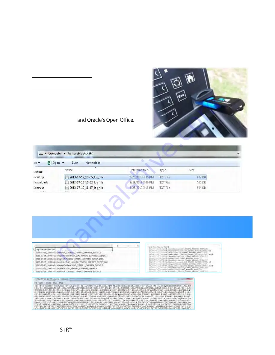
USB Interface (cont.) 

 
Each  file  saved  to  the  USB  drive  will  be  a  (.txt- 
text) file.  These files can be opened with  many 
computer  programs  to  include:  Microsoft  Excel, 
Windows Note Pad, 


The information contained in the file will be displayed in consecutive sequence and time stamped 
to the second for which the status/event occurred.  


NOTE:


Information within the file may be displayed differently, dependent upon which program the file is opened 

with.  Microsoft Excel and Word will list the events in a single column by data/time stamp, whereas Note Pad will 
display the information in block format- making it difficult to read.


Содержание PT-3500

Страница 1: ...PT 3500 PT 7500 Puller Tensioner Operators Manual...

Страница 2: ......

Страница 3: ...Precautions 16 Chemical Safety 17 Section 4 Operation 17 Terms You Need to Know 18 Safe Zone Cab 20 Operator Controls 24 Tier 4 Engine PT 3500 29 System Control Panel 33 USB Interface 35 Joystick Con...

Страница 4: ...Hydraulic Fluid 91 Replacing Hydraulic Fluid and Filters 92 Hydraulic Hose Replacement 94 Drum Reel Drive Assembly 94 Drive Shaft 94 Drive Shaft Cones 95 Drive Barn and Pins 95 Drive Couplings 96 Dri...

Страница 5: ...r Fault Issues 122 When to Send for Service or Repair 124 Section 8 Parts 124 Sherman Reilly Accessories 124 Miscellaneous Replacement Parts 127 Appendix A Manufacturer Manuals Kubota V3800TB Engine M...

Страница 6: ......

Страница 7: ...y Taking unnecessary risks and ignoring warnings is the primary cause of personal injury and fatal accidents in the work place If you have any questions regarding operation or safety of a procedure or...

Страница 8: ...d a problem or unsafe condition arise shut the machine down using the normal shut down procedure In the event of an emergency use the Emergency Stop Procedure described in this manual and then notify...

Страница 9: ......

Страница 10: ...of the levelwind also allows for easy upright standby positioning during payout and tensioning operations The PT 3500 is equipped with a turbo charged industrial Tier 4 Final diesel engine that delive...

Страница 11: ...ISO Grade 32 Hydraulic Reservoir 40 gallon 32 useable gallons Hydraulic Fluid Filtration 2 10 micron both supply and return filters Levelwind Hydraulically driven automatically controlled Safe enclos...

Страница 12: ...d maximizing rope life The horizontal floating style of the levelwind also allows for easy upright standby positioning during payout and tensioning operations The PT 7500 is equipped with a turbo char...

Страница 13: ...Reservoir 40 gallon 32 usable gallons Hydraulic Fluid Filtration 2 10 micron both supply and return filters Levelwind Hydraulically driven automatically controlled Safe enclosed single door Frame Con...

Страница 14: ...r examples Warning Terms The word DANGER indicates the information relates to a specific immediate hazard which if disregarded will result in severe personal injury or death The word WARNING indicates...

Страница 15: ...pressure oil never use your hands to check for oil leaks use paper or cardboard Hydraulic fluid escaping under pressure can have sufficient force to penetrate skin If fluid is injected into the skin i...

Страница 16: ...could impair ability or judgment Do not operate equipment if work ability is impaired by fatigue illness or other causes Always use employer approved grounding procedures when operating the machine N...

Страница 17: ...fore assigning workers to operate service or repair the machine and equipment A record of training dates employee names and level of training shall be maintained Only persons who have a full understan...

Страница 18: ...have a MSDS SDS available for work being done and would thereby be employer or the organization providing the maintenance All chemical handling and disposal should be done in accordance with environme...

Страница 19: ...draulic Tank w Filter 7 Sight Gauge 8 Hydraulic Power Engine 9 Hydraulic Pump 10 Hydraulic Drive Motor s 11 Emergency Manual Override 12 Rear Nose Jack 13 Side L R Jacks 2 14 Drum Reel 15 Drum Drive B...

Страница 20: ...reduce errors and injuries in the and also reduce environments Operators Controls Ergonomic Operators Chair Auxiliary Power Port A 12 Volt DC power port has been provided on the operator control cons...

Страница 21: ...Safe Zone Cab Climate Control System The PT Series Safe control system providing customized air temperature controls for both heating and cooling The climate control system has multiple air fan speed...

Страница 22: ...Revolution Series PT 3500 PT 7500 Puller Tensioner Page 20 Operation Operator Controls 2 ReGen Icon PT 3500...

Страница 23: ...power switch upward to the START position If the glow plugs are required they will engage automatically when the switch is placed in the ON position Exterior Work Lighting Power Switch This control sw...

Страница 24: ...desired the operator can always press the HOME button to return to the HOME screen Rotational Control Knob Button This knob when rotated controls the value of a selected variable field on the display...

Страница 25: ...dentification message showing the mode selected Engine Control Display The engine control display shows general system and operation specific information The PT 3500 is equipped with a Tier 4 Final di...

Страница 26: ...cur automatically Level 3 A PARKED MANUAL REGEN is required Level 4 5 Non warranty factory assistance from Kubota is required IMPORTANT Perform a Parked Manual REGEN BEFORE the engine reaches Level 4...

Страница 27: ...nitial start of operations if the drum is changed and when changing the rotational direction of the drum payout pull in NOTE The system is designed to automatically adjust the engine idle speed when t...

Страница 28: ...a fault is detected both the HOME Screen button and the page the selection for that fault will turn red HELP When this button is pushed it will display a screen containing helpful information about th...

Страница 29: ...neutral preventing the use of the R L jacks from inside the operator cab and disabling interior the R L jack controls NOTE The footage counter should only be reset when the line is all the way out fro...

Страница 30: ...o set the hydraulic brake However if operating at high tension settings the system may not be able to build adequate hydraulic pressure to apply the brake in the amount of time it can take the high te...

Страница 31: ...ere is no manufacturer recommendation on frequency If the brake test fails please contact the S R Service department DIAGNOSTICS This button provides the operator with several pages of live views of m...

Страница 32: ...pe Cable Drum and the optional Reconductoring Drum To do this simply push and hold the SET DRUM button This will toggle the configuration settings for the machine between the two available drum sizes...

Страница 33: ...of the rope or cable onto the drum or reel By default the system will retain the last setting used and the system contains all most common size rope diameter sizes LOGGED DATA This screen allows the...

Страница 34: ...OCK This screen gives the operator access to set the system date and time DISPLAY This button when pressed takes the operator to the Display Settings Screen Once on this screen the user can dial up or...

Страница 35: ...e USB drive into the USB port Once on the Data Recording screen and with the USB Drive inserted ensure that the message Next press the touch screen button marked MOVE DATA TO USB This will begin the t...

Страница 36: ...ter programs to include Microsoft Excel Windows Note Pad The information contained in the file will be displayed in consecutive sequence and time stamped to the second for which the status event occur...

Страница 37: ...o the center neutral position with the trigger released This allows the operator to set the line speed for extended operations without the need to constantly hold the joystick in position To rotate th...

Страница 38: ...l set halting operations It is important to know that the amount of tension applied to the line is not controlled by the joystick rather the tension setting programmed into the system by way of the ro...

Страница 39: ...yout depress the joystick trigger then push the joystick forward The farther forward the joystick is pushed the faster the reel will spin thereby increasing line speed To decrease speed pull the joyst...

Страница 40: ...sole rocker buttons first ensure that the hydraulic power engine is on and then select the DEPLOY LT RT JACKS option on the control panel screen to enable jacks Once enabled views of the jack cameras...

Страница 41: ...ng the inside control panel LEVELWIND SETUP Screen or by using the outside control panel Using the top joystick lateral rocker switch adjust the R L starting position of the levelwind so that the leve...

Страница 42: ...levelwind if needed by rotating the levelwind speed control knob CW to increase and CCW to decrease speed Spider System Levelwind The spider system levelwind controls are the same as rope drum levelw...

Страница 43: ...would usually be in tandem with outside line rigging and drum changing operations To operate the control simply push and hold the button to move the machine component When the button is released the...

Страница 44: ...e corresponding lever up To move the levelwind down push and hold the corresponding lever down When the levers are released the spring loaded valve lever will return to the center neutral position and...

Страница 45: ...Position machine and chock wheels The machine should be positioned in line with the tower and centered as much as possible on the line being pulled Wheels should be chocked to prevent rolling 3 Ensur...

Страница 46: ...ion limit on the system control display If the system is not already in the desired mode press and hold the winch mode button for three seconds to change Rotate and press the control knob to set and l...

Страница 47: ...e sections to toggle 5 Set the line tension limit prior to beginning pull The tension limit can be changed without halting operations by using the rotating control knob at the top of the display Press...

Страница 48: ...ng backward toward the operator on the joystick Pull slightly back on the joystick out of neutral and pause for about 3 seconds for the brake to release before continuing to pull backward on joystick...

Страница 49: ...l mode 6 Calibrate Input the LEVELWIND LIMIT STOPS On the Control Panel Main Menu screen Press SETUP Press LEVEL WIND LEFT SIDE Press CALIB LEV WIND LT Using the ROCKER SWITCH on top of the Joystick v...

Страница 50: ...he rope paying out Pulling backward on the joystick results in the rope being pulled in Once rotation speed is at the desired level the joystick and trigger can be released Trigger should be released...

Страница 51: ...heels on both sides of the machine unit trailer then start machine unit engine See Start Up Procedure section Make sure the right and left jacks are fully retracted See Jack Controls section Open the...

Страница 52: ...e and check o Clearance lights o Brake Lights o Turn Signals o Brakes For issues see Trailer Assembly section Remove and stow the wheel chocks Unless otherwise indicated by applicable laws posted spee...

Страница 53: ...ions however it may not be possible to achieve these distances see note below The unit should be leveled as much as possible centered on the lead block and parallel to the line being pulled prior to b...

Страница 54: ...evel and stabilize the machine using the available hydraulic jacks see Jack Controls section Properly anchor the machine to prevent the machine from moving under tension or line load NOTE Before begin...

Страница 55: ...nel If necessary while outside of the cab attach the pulling rope to the tow vehicle Get back inside the cab and turn off the automatic levelwind control using the door panel rocker switch Select PULL...

Страница 56: ...conductor lines attached to this machine the operator must ensure that the hydraulic drum brake is set and the joystick is in the neutral position with the joystick trigger released NOTE To stop drum...

Страница 57: ...for the system If the system is already in TENSION MODE then there is no need to change this setting Set the tension limit for the machine using the rotational control knob Once the tensioned is set...

Страница 58: ...To stop drum rotation at any time return the joystick control to the center neutral position with the joystick trigger released and the hydraulic drum brake will set CAUTION Before handling any pilot...

Страница 59: ...ing grips attached to opposite sides of swivel on the conductor side Get back inside the cab and turn on the automatic levelwind control using the door panel rockers switch Ensure that the levelwind f...

Страница 60: ...igger then pull back slightly on the joystick bringing it out of neutral and then pause for about three seconds for the brake to release Once the brake is released release the joystick trigger and con...

Страница 61: ...or the brake to release Once the brake releases with the joystick trigger still depressed cross over neutral by pushing the joystick forward Once the joystick has crossed over neutral release the joys...

Страница 62: ...trigger released the hydraulic drum brake is set shownon screen then using a tie off rope around the drum secure the rope end to the drum Raise all jacks prior to transport If tools were used during o...

Страница 63: ...drive pin nuts jto hold them in place in line with the holes NOTE When transitioning from a rope drum to a conductor reel ensure that the rope end is secured to the drum using a tie off rope around t...

Страница 64: ...al Lift the conductor reel reconductoring drum and place into the machine drive assembly seating the drive shaft into both of the bottom drive coupling halves With the lifting straps chains still atta...

Страница 65: ...n the system control display by pressing and holding the SELECT MODE button for three seconds This setting is defaulted to whatever was last set for the system If the system is already in TENSION MODE...

Страница 66: ...lows the hydraulic system time to build enough pressure to sustain any pre existing line tension before releasing the brake This is a safety feature of the system that prevents the drum from rapidly p...

Страница 67: ...drum reel is installed the operator can lower the levelwind arm using the outside hydraulic control panel If operations are completed secure the levelwind to the frame using a tie down or rope Raise a...

Страница 68: ...uctor reel Guide Arm Loop Spider System Operations 1 From the HOME screen Press SETUP ABOUT then the ENABLE DISABLE button to enable SPIDER WIND 2 Set the SPIDER CONTROL to ON a Press and Hold the SEL...

Страница 69: ...ss LEVEL WIND LEFT SIDE Press CALIB LEV WIND LT Using the ROCKER SWITCH on top of the Joystick visually position the Levelwind Loop to the Left desired limit Press and Hold CALIB LEV WIND LT until it...

Страница 70: ...ing forward on the joystick results in the rope paying out Pulling backward on the joystick results in the rope being pulled in Once rotation speed is at the desired level the joystick itself can be r...

Страница 71: ...t comes standard with a fire extinguisher mounted somewhere on the equipment for quick access by the operator However should a fire occur with S R equipment the operator should only utilize the provid...

Страница 72: ...ning control valve seals bad Motor off or holding valve on jack is malfunctioning UNIT WILL NOT BUILD MAXIMUM HYDRAULIC SYSTEM PRESSURE restricting hydraulic pressure Control valve blocked or malfunct...

Страница 73: ...rt on the PVG valve is in fault Check 5 volt sensor power ground to and sensor input Check harness connection Level Wind Position The angle sensor for level wind arm position is outside the fault chec...

Страница 74: ...e charge filter normally closed switch is open indicating bypass Hydraulic oil temperature must also be greater than 80 degF for this fault to occur Contact Sherman Reilly service representative Brake...

Страница 75: ...r Level Wind Valve Voltage output for PVG valve CVA 7418 Section 1 is open or shorted Fault maintains when true repower control to clear Check harness connection at valve continuity or shorts between...

Страница 76: ...connection in harness Fault maintains when true repower control to clear Right Jack Lower Valve Right jack valve in the retract direction CVA 7418 Section 4 is open or shorted Fault maintains when tr...

Страница 77: ...control to clear Check harness connection at valve continuity or shorts between pins and ground connection in harness Fault maintains when true repower control to clear Spider Pay In Valve Directional...

Страница 78: ...g to the below table with a tolerance of approximately 5 unless other specific torque rating is noted in this manual The below table is for advisory purposes only General Recommended Torque for Fasten...

Страница 79: ...ening torque should be set according to the below table with a tolerance of approximately 5 unless other specific torque rating is noted in this manual The below table is for advisory purposes only Ge...

Страница 80: ...xterior Work Lights 25 Amp Hydraulic Cooler 2 Amp Main System Power 2 Amp System Display Memory 20 Amp System Display 50 Pin PLC 20 Amp 30 Pin PLC 25 Amp A C Heater Main 25 Amp A C Condenser Fan 10 Am...

Страница 81: ......

Страница 82: ...S R Revolution Series PT 3500 PT 7500 Puller Tensioner Page 78 Troubleshooting Fuse Relay Wiring Schematic...

Страница 83: ...S R Revolution Series PT 3500 PT 7500 Puller Tensioner Page 79 Troubleshooting...

Страница 84: ...S R Revolution Series PT 3500 PT 7500 Puller Tensioner Page 80 Fuse Relay Wiring Schematic...

Страница 85: ...S R Revolution Series PT 3500 PT 7500 Puller Tensioner Page 80 Troubleshooting PT Trailer Wiring Schematic...

Страница 86: ...S R Revolution Series PT 3500 PT 7500 Puller Tensioner Page 80 Troubleshooting PT Trailer Wiring Schematic...

Страница 87: ...S R Revolution Series PT 3500 PT 7500 Puller Tensioner Page 81 Troubleshooting Hydraulic Schematic 7500...

Страница 88: ...S R Revolution Series PT 3500 PT 7500 Puller Tensioner Page 81 Troubleshooting PT Hydraulic Schematic...

Страница 89: ......

Страница 90: ...tenance of the machine All inspections and preventive maintenance described in this section are deemed as critical to the safe operation of the machine and should be regarded as such The indicated int...

Страница 91: ...ing devices chains slings and hooks are in good condition and have the rated capacity to safely handle the work to be performed Use guide lines when necessary for control during the lifting process Al...

Страница 92: ...rt construction and rope blocks should be inspected by an expert before being put into operation for the first time as well as after having undergone substantial modification Machines including their...

Страница 93: ...k In Period The hydraulic filters should be replaced after the first 25 hours of operation and as outlined in the Preventive Maintenance Schedule section Only use ISO Grade 32 hydraulic fluid When add...

Страница 94: ...event contamination or damage to the system Hydraulic System Hose Inspection Check the outer surface of the hoses for damages e g tears bends cuts loosened parts abrasions brittle spots etc Check the...

Страница 95: ...es within the HIGH LOW limits of the sight gauge about of the way full just below the HIGH mark is recommended Replace and tighten the fluid reservoir access cap panel NOTE If adding a small amount of...

Страница 96: ...s will open the valve allowing the hydraulic fluid to flow from the center of the drain plug without having to remove the entire plug The drain cock is located on the drain plug at the bottom of the h...

Страница 97: ...panel to access the return filter assembly Remove the filter assembly and spring from the tank casement Holding the top or middle of the filter assembly and using a crescent wrench rotate the bottom...

Страница 98: ...the rubber O ring on the top half of the assembly by wiping it with a clean dry cloth Inspect the O ring for damage If damaged remove it and replace with a new O ring prior to installing the new filt...

Страница 99: ...center hole until it reaches within the HIGH LOW limits of the sight gauge about of the way full just below the HIGH mark is recommended see Adding Hydraulic Fluid section CAUTION Make sure hydraulic...

Страница 100: ...reads Continue tightening the mounting screws in a crisscross pattern using a in wrench until snug Filter kits are available from S R See the Parts Section for replacement part numbers NOTE Filters sh...

Страница 101: ...ure there is no damage to threads Carefully thread new hose to fitting and tighten Refill tank as needed to replenish any lost hydraulic fluid using sight gauge for proper level see Adding Hydraulic F...

Страница 102: ...ct Sherman Reilly Service Department for service see Service Repair section Drive Shaft Cones and Set Collars Drive shaft tapered cones are installed on both sides of the drive shaft to prevent uneven...

Страница 103: ...ing Drive Couplings The drive shaft seats into the drive couplings on both sides of the machine Each drive coupling is split horizontally into two halves The top half of the coupling is removable with...

Страница 104: ...d for damage and torqued to 400 ft lbs in accordance with the preventive maintenance schedule Inspect the sensor connection to ensure that there is no damaged Inspect the sensor wires for frayed or cu...

Страница 105: ...h operation to ensure that it is secured to the frame and that there are no visible signs of damage The pillow block mounting bolts nuts should be inspected for damage prior to operations and torqued...

Страница 106: ...d also be inspected to ensure they are in place and tight prior to operation Greasing Pillow Block Bearings The pillow block bearing must be properly lubricated with lithium base Grade 2 all purpose g...

Страница 107: ...e schedule See below for specified torque values follow standard recommended torque values for all other values not specified here Motor Mount Screws Bottom 3 4 10UNCx2 25 GR5 227 lbs Back 5 8 11UNCx3...

Страница 108: ...Break In Period The engine oil and oil filter should be replaced after the first 50 hours of operation and as outlined in the Preventive Maintenance Schedule section and engine Always premix the corr...

Страница 109: ...the climate control system compressor condenser fans hoses etc Climate control system should be regularly inspected for damages and leaks NOTES Any maintenance or modifications to the climate control...

Страница 110: ...and then every 3 000 miles thereafter see self adjusting instructions in For all additional inspection cleaning adjustment and replacement instructions see Towing Prior to towing the trailer must be h...

Страница 111: ...d in accordance with the maintenance schedule to ensure safe towing operations see Preventive Maintenance Schedule section For all additional inspection cleaning adjustment and replacement CAUTION Whe...

Страница 112: ...or to towing or moving the trailer Axle drum oil should be just below oil cap plug hole If axle drum oil level is low remove axle drum oil cap plug pour in fluid until fluid level is just below oil ca...

Страница 113: ...ensure they work prior to transport For replacement see Parts section If none of the lights work Check vehicle trailer wire connectors for damage or corrosion The vehicle trailer wire connectors can v...

Страница 114: ...s dependent upon the light Pop out the lighting pod from its rubber grommet holder by pushing from the inside toward the outside or pushing in from the outside and reaching into the hole to pull the p...

Страница 115: ...port cut in the engine cowling After checking oil level wipe dipstick clean of any debris prior to reinserting into spout 5 Ensure proper hydraulic fluid level in reservoir for hydraulic system by vi...

Страница 116: ...of damage leaking hydraulic cylinders or hoses and ensure rollers move freely 10 Inspect all equipment grounds for any signs of damage 11 Inspect all jacks for damage or leaking hydraulic components...

Страница 117: ...place to prevent accidental discharge d Ensure that the plastic safety seal is secured to hinge pin and that it has not been removed e Inspect mounting strap bracket assembly to ensure extinguisher i...

Страница 118: ...tools equipment used during operations back into the tool box Then close and lock tool box 6 Secure the rope end to the drum using a tie off rope around the drum Also secure the levelwind to the rear...

Страница 119: ...ve any trash rags or other loose material from the machine to keep the machine clean and so as not to create a fire hazard Storage For periods of extended storage without use the manual ignition switc...

Страница 120: ...ufacture s manual for complete maintenance schedule and instructions See Appendix A instructions See Appendix Tier 4 Final Engine Compliance For all Tier 4 final engines maintenance intervals and inst...

Страница 121: ...ver comes first All Inspect Tire Condition Inspect tires for wear and damage every 3 months 3 000 miles see Tires section All Check Torque on Wheel Nuts and Bolts Tighten to specified torque values ev...

Страница 122: ...2 All Purpose Grease see Drum Reel Drive Assembly section PT 3500 Clean Engine Air Filter Element Clean filter element every 100 hours and only use less than 30 psi compressed air PT 3500 Drain the F...

Страница 123: ...anings Replace sooner if damaged or heavily discolored see Engine Manual PT 3500 Check Engine Coolant Hoses and Clamps Inspect radiator hoses and clamps for signs of damage wear and leaks Also ensure...

Страница 124: ...mage wear and leaks Also ensure they are secured see Engine Manual PT 7500 Check of Engine Air Intake Inspect air intake lines for the engine and ensure no damage or obstructions PT 7500 Clean Engine...

Страница 125: ...cate Key Tumblers and Switches Use only graphite powder in key tumblers and switches to lubricate internal keyhole parts and prevent sticking of keys PT 7500 Replace Engine Fuel Filter Cartridge See E...

Страница 126: ...fter 2 500 working hours or every 10 years starting from the year of construction of the machine see Equipment Information for manufacturer date Every 3 000 Hours of Use All Check Engine Turbo Charger...

Страница 127: ...set according to the below table with a tolerance of approximately 5 unless other specific torque rating is noted in this manual The below table is for advisory purposes only General Recommended Torqu...

Страница 128: ...e tightening torque should be set according to the below table with a tolerance of approximately 5 unless other specific torque rating is noted in this manual The below table is for advisory purposes...

Страница 129: ...Revolution Series PT 3500 PT 7500 Puller Tensioner Page 121...

Страница 130: ...ations the machine would create an unsafe condition further or and safely operate the machine When to send for Service or Repair If after troubleshooting an issue or fault that cannot be resolved or a...

Страница 131: ...Revolution Series PT 3500 PT 7500 Puller Tensioner Page 123...

Страница 132: ...0 ft Uniline Rope with Grip Swivel 602546 44 x 21 000 ft Unitrex Rope with Eye Splice 602547 PT 7500 63 x 11 500 ft Unitrex Rope with Eye Splice 601410 1 in x 5 500 ft Uniline Rope with Grip Swivel 60...

Страница 133: ...Revolution Series PT 3500 PT 7500 Puller Tensioner Page 125...

Страница 134: ...Revolution Series PT 3500 PT 7500 Puller Tensioner Page 126 A...

Страница 135: ...nual Kubota V3800T Engine Manual Dexter Axle Manual Appendixes are located on a CD and may not be included with this manual If not included contact Sherman Reilly Parts Service Department at 1 800 251...

Страница 136: ...inspections and evaluations The information contained represents the best practices for the safest use and maintenance of the machine unit and does not cover every situation With regard to situations...

Отзывы: