


www.ti.com
9.8.3
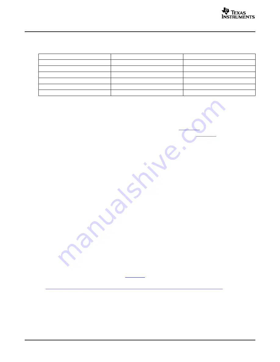
TCI6482 Timers vs TCI100 Timers
9.9
EDMA3
9.9.1
Configuration of EDMA3
9.9.2
System Implementation
9.9.3
TCI6482 EDMA3 vs TCI100 EDMA
9.10 Inter-Integrated Circuit (I
2
C)
9.10.1
Configuration of I
2
C
Peripheral Section
Table 22. Timer Comparison: TCI6482 vs TCI100
TCI6482
TCI100
Default condition (if selected)
Disabled
Enabled
Number of Timer modules
2
3
Timer size (each)
1 @ 64-bits, 2@ 32-bits
32 bits
Watchdog functionality
Yes
No
Internal Timer clock frequency
CPU core clock / 6
CPU core clock / 8
64 bit free running CPU counter
Yes
No
Documentation for EDMA3:
•
EDMA v3.0 (EDMA3) Migration Guide for TMS320TCI648x DSP (
SPRAAC1
)
•
TMS320TCI648x DSP Enhanced DMA (EDMA3) Controller User's Guide (
SPRU727
)
The EDMA is enabled after a reset.
The EDMA is clocked at CPU core clock / 3.
Configuration across the EDMA may not take affect immediately. In order to make sure that a peripheral
configuration has completed before accessing that peripheral it is recommended to setup an interrupt to
occur after the DMA has completed. After the interrupt is asserted the peripheral can be accessed.
The FIFO addressing mode of the EDMA3 channel controller is not supported by any of the peripherals on
the TCI6482 device, therefore, increment addressing mode should always be used. The migration
document referenced above gives a complete overview of the differences between the TCI6482 and the
TCI100 EDMA implementations.
Documentation for I
2
C:
•
TMS320TCI648x DSP Inter-Integrated Circuit (I2C) Module User's Guide (SPRUE11)
•
TCI6482 System Boot
•
TCI6482 IBIS Model File
•
Using IBIS Modes for Timing Analysis (
SPRA839
)
•
Philip's
I2C
Version
2.1
Specification:
http://www.semiconductors.philips.com/acrobat_download/literature/9398/39340011.pdf
The I²C peripheral needs to be enabled via software before use. The input clock for the I²C module is core
clock / 6. There is a prescaler in the I²C module that needs to be setup to reduce this frequency to an
internal module clock of 7 to 12MHz.
If the I²C signals are not used, the SDA and SCL pins can be left floating. This does cause a slight
increase in power due to leakage which can be avoided by having pull-up resistors.
TMS320TCI6482 Design Guide and Migration from TMS320TCI100
32
SPRAAC7B – April 2006
Submit Documentation Feedback


