


www.ti.com
9.1.3
TCI6482 EMIFA vs TCI100 EMIFA
9.2
Host Port Interface (HPI) Memory Access
9.2.1
Configuration of HPI
Peripheral Section
Table 11
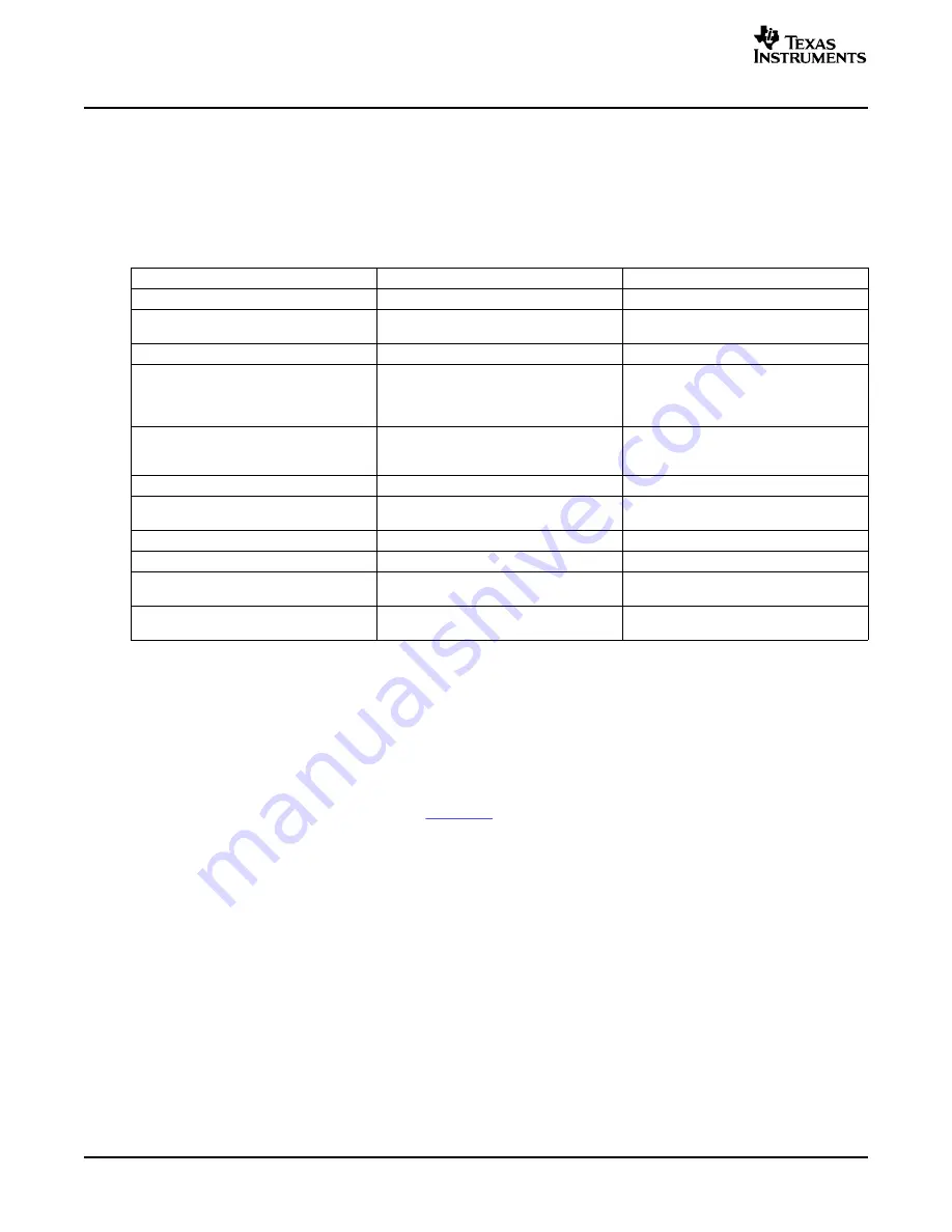
shows a comparison between the EMIFA features of the TCI6482 and the TCI100. The EDMA3
FIFO addressing mode is not supported so incrementing addressing is always used. This may require not
connecting lower address lines when attaching a device with a FIFO interface to the TCI6482 EMIFA
interface. The AC timings for the TCI6482 are similar to TCI100 but there are some differences. Refer to
the TCI6482 data manual to check AC timings.
Table 11. EMIFA Comparsion: TCI6482 vs TCI100
TCI6482
TCI100
Default condition (if enabled)
Disabled
Enabled
Programmable Synchronous Mode
ü
ü
(SBSRAM, ZBT, FIFO)
Asynchronous Mode (ROM, SRAM)
ü
ü
Addressable Ranges
64-bit: 8MB
64-bit: 8MB
32/16/8-bit: 4MB
32-bit: 4MB
16-bit: 2MB
8-bit: 1MB
ARDY features
Can be disabled, polarity is programmable
Always enabled and always active high
Lack of ARDY timeout supported, can
Wait states can lock up the interface
generate interrupt
indefinitely
Support for late write SRAM
ü
EMIF Boot Feature
(executes from CE3 space)
ü
(1K ROM coopied to L2, then executed)
SDRAM Mode
ü
PDT Transfers
ü
Clocking Options
AECLKIN,
AECLKIN,
SYSCLK4 (internal divider)
Core clock/4, Core clock/6
Buffer Impedance
25 Ohms (data and AECLKOUT)
25 Ohms
50 Ohms (control)
Documentation for HPI:
•
TMS320TCI648x DSP Host Port Interface (HPI) User's Guide (SPRU874)
•
TCI6482 System Boot
•
TCI6482 IBIS Model File
•
Using IBIS Modes for Timing Analysis (
SPRA839
)
The HPI interface is multiplexed with the PCI inteface. Selection between HPI and PCI is done via boot
strapping and latched by reset. If HPI is selected, a second boot strapping options selects the HPI bus
width as either 16 bit or 32-bit. The supported Boot over HPI option is selected by boot strapping as well.
Refer to the TCI6482 data manual for details on the strapping options.
Internally the HPI module is clocked by SYSCLK3, which is CPU core clock / 6. Therefore, the maximum
HPI timing is somewhat dependent on the CPU core clock frequency.
If neither HPI nor PCI is used, either PCI or HPI mode can be selected by the boot strapping and the
signals may be no-connects (as long as the peripheral is not enabled via the peripheral configuration
register). However, there may be additional power consumption when inputs are left floating. This can be
avoided by putting pull-up resistors on unused inputs.
If only a portion of the interface is used (i.e. HPI16 mode), control signals should be pulled to an
appropriate state and unused data signals can be left floating, although the power consumption will be
higher than if external pull-ups are used on these data signals.
TMS320TCI6482 Design Guide and Migration from TMS320TCI100
24
SPRAAC7B – April 2006
Submit Documentation Feedback


