LE910-SKG AT commands reference guide
80437ST10619A Rev.1 – 2014-09-16
Reproduction forbidden without Telit Communications S.p.A. written authorization - All Rights Reserved
page 149 of 273
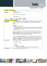
#GPIO - General Purpose Input/Output Pin Control
OK
AT#GPIO=4,1,1
OK
AT#GPIO=5,0,0
OK
AT#GPIO=6,2
#GPIO: 0,1
OK
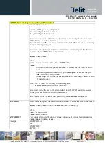
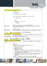
#ALARMPIN – Alarm Pin
AT#ALARMPIN=
<pin>
Set command sets the GPIO pin for the ALARM pin
Parameters:
<pin>
defines which GPIO shall be used as ALARM pin.
For the
< pin >
actual range check the “Hardware User Guide”. Default value is 0,
which means no ALARM pin set.
Note: the setting is saved in NVM
Note: ALARM pin function of a GPIO corresponds to ALT2 function of the
GPIO. So it can be also set through AT#GPIO command, ALT2 function.
AT#ALARMPIN?
Read command returns the current parameter settings for #ALARMPIN command
in the format:
#ALARMPIN:
<pin>
AT#ALARMPIN=?
Test command reports the supported range of values for parameter <pin>.
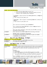
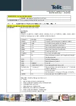
#SLED - STAT_LED GPIO Setting
AT#SLED=<mode>
[,<on_duration>
[,<off_duration>]]
Set command sets the behaviour of the
STAT_LED
GPIO
Parameters:
<mode>
- defines how the
STAT_LED
GPIO is handled
0 - GPIO tied
Low
1 - GPIO tied
High
2 - GPIO handled by Module Software (factory default) with the following
timings:
not registered : always on
registered in idle: blinking 1s on and 2s off
registered in idle with powersaving : blinking time depends on network
condition in order to minimize power consumption
3 - GPIO is turned on and off alternatively, with period defined by the sum
<on_duration> + <off_duration>
4 - GPIO handled by Module Software with the following timings:
not registered : blinking 0,5s on and 0,5s off
Содержание LE910-SKG
Страница 1: ......


