40
ECO II FEEDING rev.06
ECO II FEEDING
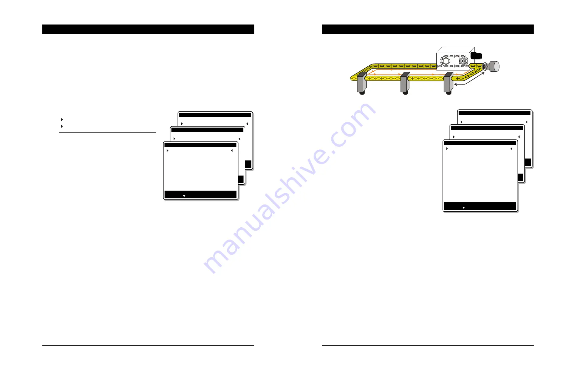
5.8 Drop Settings
The user must specify on which loop each drop is located and the distance between
the drop and the feed’s entry point. This way, the controller coordinate the opening
and closing of the drops so that each drop receives the proper feed batch.
Up to 96 drops can be enabled; each drop can feed approximately 25 feeders. Refer to
the graphics shown in section 2.3. Refer to section 5.3 to activate the proper number
of drops.
Select
11. Installation *
5. Drop Settings
* Accessible from the installer mode (s. 5.2).
• Select a drop
Following parameters are associated
with the chosen drop and must be set
separately for each drop in use.
• Loop #:
Select on which loop the selected drop
is located.
• Distance from feed entry:
Enter the distance (in feet) that separates the drop from its feed’s entry point.
• Drop’s Module ID:
Select on which relay panel the selected drop is connected; the relay panel is
identified by its ID number (ID #4 to ID #19). Tables are available at the end of
this manual to write down the identification number of each module.
• Drop’s Output #:
Select on which relay the selected drop is connected (relay 1-16). If the
output is connected to relays 17-32 of a 32 output relay panel, select on which
relay of the second 16-relay strip the output is connected; i.e., relay 17=1,
relay 18=2... relay 32=16. Refer to section 5.9 for further information
• Has proximity Switches ?
Select “Yes” if the holding hopper has proximity sensor(s) (refer to the graphic
below). These sensors are only needed if the AdLib feeding method is used.
* Available if the “Continuous Feeding” option is disabled in section 5.3. When this mode is used, proximity
switches are not optional, they are automatically enabled.
Main Menu
10.
Alarm acknowledge
11.
Installation
Installation
4.
Bin settings
5.
Drop settings
Drop settings
Exit: Press BACK
Change: Press Modify
Press to Select an item
Select Drop #
1
Loop #
1
Distance from feed entry
1
Module ID
4
Output #
7
Has Prox switches
Yes
Min Prox switch module ID
27
Min Prox switch Input #
1
Max Prox switch module ID
27
Max Prox switch Input #
2
Inter-batch delay (mm:ss) 0:00
Max Capacity
7 kg
37
ECO II FEEDING rev.06
ECO II FEEDING
• Max current (if closed loop)
This is the maximum allowable current
consumption of the loop’s motor.
• Actual current (if closed loop)
This is the motor’s actual current
consumption. This value is displayed
as a reference only, it cannot be modi-
fied.
•
Over-current delay (if closed loop)
An alarm is set off if the loop’s motor
consumption still exceeds the maxi-
mum current limit after this delay has
elapsed. Adjustable from 1 second to
4 minutes. The entire feeding will stop
if this delay is exceeded.
• Proximity switch off delay (if closed loop)
An alarm is set off if feed is being detected by the loop’s proximity sensor for
a time period that exceeds this delay.
• Proximity switch bypass delay (if closed loop)
When a feeding cycle ends, a little amount of feed can remain at the end of
the distribution line. A delay is defined to allow the evacuation of this feed
when a new cycle starts: the proximity switch ignores the presence of feed
during the bypass delay. Adjustable from 0 seconds to 4 minutes.
• Has fill auger ? (if closed loop)
Set to “Yes” if a fill auger is used to bring the feed blends into the loop. This
option is normally used if two closed-loop systems are used. Refer to the
graphic shown in section 2.3.
Main Menu
10.
Alarm acknowledge
11.
Installation
Installation
2.
Scale settings
3.
Loop settings
Loop settings
Exit: Press BACK
Change: Press Modify
Press to Select an item
Select loop #
1
Loop speed
100 ft/mn
Min distance betwn feeds
25 ft
Loop slip
0 %
Valve open/close time
4 sec
Is flex auger ?
No
Max current
9.5 A
Actual current
0.0 A
Over-current delay
3:00 (m:s)
Prox switch off delay
0:00 (m:s)
Prox switch bypass delay
1:00 (m:s)
Has fill auger ?
Yes
Flex auger Module ID
4
Flex auger Output #
5
Prox switch Module ID
20
Prox switch Output #
6
D
R
O
P
Feed
bypass
delay


