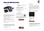
Figure 2.1.1
1. “STANDBY” button with indicator
a. Switches to red in standby mode;
b. Switches to blue when operating.
2. Menu display
2.8” 320×240 LCD displays main unit status and
configuration menu.
3. Function knob
a. The LCD displays the initial user interface: rotate
this knob to adjust master volume;
b. The LCD displays the initial user interface: press
this knob to enter the menu;
c. The LCD displays the set-up user interface: rotate
this knob to select the menu item, the selected
menu item red highlighted;
d. The LCD displays the set-up user interface: press
this knob (equivalent to entering or confirming
button) to select the red highlighted item or enter
the next menu;
e. The LCD displays the network configuration:
press this knob to select / uncheck the value,
rotate this knob to adjust the value size.
4. Ethernet interface (LAN)
For communication between the conference main
unit and the PC under TCP/IP protocol to realize
remote controlling; furthermore, it enables remote
controlling by wireless touch panel through central
control system.
5. Extension interface
To interconnect CMU, EMUs, audio input
interfaces and audio output devices – units
already prepared for cascade connecting.
6. Fiber interface
Single-mode optical fiber, SC connector;
Connecting the conference main units of several
distant conference rooms to combine as one
conference room (bridging distance can reach
tens of kilometers).
7. Contribution units (CU) connection LED
When output works properly (
≥ 1 CU connected),
LED will flash; when no CU is connected, LED is
off.
8. Contribution units output interface (1-2, two
routes)
9. Mini USB interface
For connecting to PC, to HCS-9000M series main
unit, conveniently connect local conference to
TAILINK cloud video conference system.
10. Group output interface (1-6, six groups)
11. HDMI input
12. HDMI loop output
13. Type-A USB recording interface
Insert U-disk for storing recording files
14. Headphone monitoring jack
Earphone jack (Ø 3.5 mm);
For monitoring USB audio.
15. Dante interface
Connecting the conference main unit to the
Dante network to transmit input and output audio
signals.
16. RS-232C port
“COM” port is used for connecting to a central
control system for central controlling, as well as for
system diagnosis.
17. LINE IN 1 / MIC IN
(3 cord XLR balanced input)
18. “LINE IN 2”
(RCAx2 unbalanced input)
19. “LINE OUT 1”
(3 cord XLR balanced output)
20. “LINE OUT 2”
(RCAx2 unbalanced output)
21. AES IN
22. AES OUT
23. Mains switch
24. Power supply
100 - 240 V, 50/60 Hz.
25. Fixed hole of the cabinet installation
14
Содержание HCS-8600 Series
Страница 1: ...Paperless Multimedia Congress System Installation and Operating Manual V 1 0...
Страница 14: ...Figure 1 1 4 HCS 8668 Series Paperless Multimedia Congress System connection diagram 3...
Страница 69: ...Figure 3 2 7 Daisy chain connection between HCS 8668 8638 series Paperless Multimedia Congress Terminals 58...
Страница 91: ...3 3 2 Fixed installation Figure 3 3 2 Fixed installation of HCS 8665 series congress unit 80...
Страница 99: ...3 4 2 Installation Figure 3 4 2 Fixing of HCS 8635 series compact multimedia congress terminal 88...
Страница 109: ...4 1 Functions and indications Front Side Bottom Figure 4 1 HCS 8685 Interpreter unit 98...
Страница 118: ...Blue 107...
Страница 138: ...Figure Audio parameter setting Normal Figure Audio parameter setting PEQ Figure Audio parameter setting DRC 127...
Страница 145: ...Figure 6 2 3 HCS 8668 Series Paperless Multimedia Congress System connection diagram POE 134...
Страница 180: ...Appendices Custom made cables Appendix Ethernet Cable 169...
Страница 181: ...Appendix CBL4PK 01 Power Adapter Cable 170...
Страница 182: ...Appendix CBL4PT 02 Power Branch Cable 171...
Страница 183: ...Appendix CBL4PS 4 pin Extension Cable 172...