


9A-4 Wiring Systems:
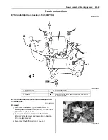
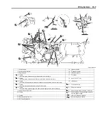
Wiring Harness Routing Diagram (LT-A750XP/ZK9)
B931G49102004
“b”
2
3
3
“B”
2
1
4
7
6
5
VIEW A
“A”
1
“a”
“b”
1
1
“c”
“D”
8
9
“C”
7
FWD
I931G3910905-02
1. Clamp
9. Throttle cable
2. Clamp
: Bind the wiring harness and hose with the clamp.
“B”: Pass the wiring harness and cooling fan lead wire over the radiator
hose.
3. Clamp
: Bind the wiring harness and cooling fan thermo switch with the clamp.
“C”: To power source.
4. Clamp
: Bind the wiring harness and back up relay (For P-17) with the clamp.
“D”: Pass the wiring harness under of the throttle cable.
5. Clamp
: Bind the EPS motor lead wire and EPS control unit lead wires.
“a”: 60 – 80 mm (2.4 – 3.2 in)
6. EPS control unit
“b”: 20 – 30 mm (0.8 – 1.2 in)
7. EPS motor
“c”: 10 – 15 mm (0.4 – 0.6 in)
8. Ignition coil
Содержание 2009 LT-A750XK9
Страница 2: ......
Страница 4: ......
Страница 5: ...SUPPLEMENTS L LT A750XK9 09 MODEL 10 LT A750XPK9 09 MODEL 11 ...
Страница 29: ...0A 15 General Information 99565 01010 013 CD ROM Ver 13 ...
Страница 57: ...0B 28 Maintenance and Lubrication 09915 40610 Oil filter wrench Page 0B 12 Page 0B 12 ...
Страница 68: ...0C 11 Service Data ...
Страница 310: ...1K 5 Exhaust System ...
Страница 482: ...4D 6 Parking Brake ...
Страница 528: ...6B 13 Steering Handlebar ...
Страница 555: ...Exterior Parts 9D 1 Body and Accessories Exterior Parts Repair Instructions Exterior Parts Construction B831G29406001 ...
Страница 581: ......
Страница 631: ...4A 6 Brake Control System and Diagnosis ...