


3D-2 Propeller Shafts:
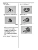
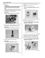
4) Remove the front output shaft (1) from the right
crankcase.
Installation
Install the front output shaft in the reverse order of
removal. Pay attention to the following point:
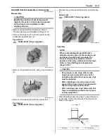
• Apply engine oil to the front output bearing (rear).
• Apply a small quantity of grease to the O-ring (1).
CAUTION
!
Replace a O-ring (1) with a new one.
: Grease 99000–25010 (SUZUKI SUPER
GREASE A or equivalent)
• Install the front output shaft to the right crankcase.
Tighten the front output shaft bolts.
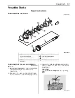
Front Output Shaft Disassembly and Assembly
B831G23406003
Refer to “Front Output Shaft Removal and Installation
(Page 3D-1)”.
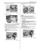
Disassembly
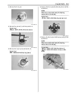
1) Remove the C-ring (1) and snap ring (2).
Special tool
: 09900–06107 (Snap ring pliers)
2) Remove the front drive collar (3), front drive output
shaft housing (4) and O-ring (5).
1
I831G1340003-02
I831G1340097-01
1
I831G1340098-01
I831G1340004-02
1
2
I831G1340005-02
4
5
3
I831G1340006-02
Содержание 2009 LT-A750XK9
Страница 2: ......
Страница 4: ......
Страница 5: ...SUPPLEMENTS L LT A750XK9 09 MODEL 10 LT A750XPK9 09 MODEL 11 ...
Страница 29: ...0A 15 General Information 99565 01010 013 CD ROM Ver 13 ...
Страница 57: ...0B 28 Maintenance and Lubrication 09915 40610 Oil filter wrench Page 0B 12 Page 0B 12 ...
Страница 68: ...0C 11 Service Data ...
Страница 310: ...1K 5 Exhaust System ...
Страница 482: ...4D 6 Parking Brake ...
Страница 528: ...6B 13 Steering Handlebar ...
Страница 555: ...Exterior Parts 9D 1 Body and Accessories Exterior Parts Repair Instructions Exterior Parts Construction B831G29406001 ...
Страница 581: ......
Страница 631: ...4A 6 Brake Control System and Diagnosis ...