


Engine General Information and Diagnosis: 1A-50
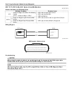
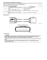
C21 (Use of mode select switch)
Step
Action
Yes
No
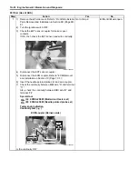
1
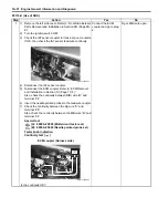
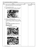
1) Remove the left side cover. Refer to “Front Side Exterior
Parts Removal and Installation in Section 9D (Page 9D-
6)”.
2) Turn the ignition switch OFF.
3) Check the IAT sensor coupler for loose or poor contacts.
If OK, then measure the IAT sensor voltage.
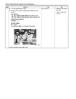
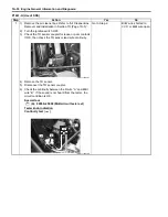
4) Disconnect the coupler and turn the ignition switch ON.
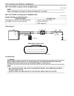
5) Measure the voltage between the Dg wire terminal and
ground.
If OK, then measure the input voltage between Dg wire
terminal and B/Br wire terminal.
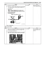
Special tool
(A): 09900–25008 (Multi-circuit tester set)
Tester knob indication
Voltage (
)
IAT sensor input voltage
4.5 – 5.5 V
((+) terminal: Dg – (–) terminal: Ground, (+) terminal:
Dg – (–) terminal: B/Br)
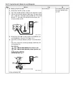
Is the voltage OK?
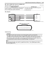
Go to Step 2.
• Loose or poor
contacts on the ECM
coupler.
• Open or short circuit
in the Dg wire or B/Br
wire.
I831G1110051-01
(A)
V
I831G1110052-02
Содержание 2009 LT-A750XK9
Страница 2: ......
Страница 4: ......
Страница 5: ...SUPPLEMENTS L LT A750XK9 09 MODEL 10 LT A750XPK9 09 MODEL 11 ...
Страница 29: ...0A 15 General Information 99565 01010 013 CD ROM Ver 13 ...
Страница 57: ...0B 28 Maintenance and Lubrication 09915 40610 Oil filter wrench Page 0B 12 Page 0B 12 ...
Страница 68: ...0C 11 Service Data ...
Страница 310: ...1K 5 Exhaust System ...
Страница 482: ...4D 6 Parking Brake ...
Страница 528: ...6B 13 Steering Handlebar ...
Страница 555: ...Exterior Parts 9D 1 Body and Accessories Exterior Parts Repair Instructions Exterior Parts Construction B831G29406001 ...
Страница 581: ......
Страница 631: ...4A 6 Brake Control System and Diagnosis ...