


1H-7 Ignition System:
Ignition Switch Removal and Installation
B831G21806008
Removal
1) Remove the left inner fender. Refer to “Front Side
Exterior Parts Removal and Installation in Section
9D (Page 9D-6)”.
2) Remove the combination meter cover. Refer to
“Combination Meter Removal and Installation in
Section 9C (Page 9C-3)”.
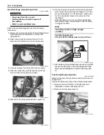
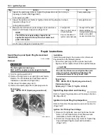
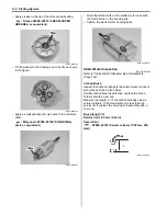
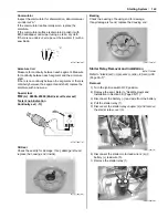
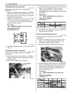
3) Disconnect the clamps and ignition switch coupler
(1).
4) Disconnect the clamp and remove the ignition switch
(2).
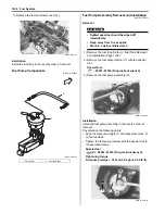
Installation
Install the ignition switch in the reverse order of removal.
Pay attention to the following point:
• Route the wiring harness properly. Refer to “Wiring
Harness Routing Diagram in Section 9A (Page 9A-4)”.
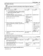
Override Switch Inspection
B831G21806009
1) Remove the left inner fender. Refer to “Front Side
Exterior Parts Removal and Installation in Section
9D (Page 9D-6)”.
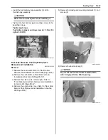
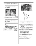
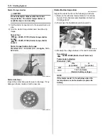
2) Disconnect the override switch read wire coupler.
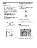
3) Check the continuity B/W wire and Br wire of the
override switch and pushing the override switch. If
any abnormality is found, replace the left handle
switch assembly with a new one.
Special tool
: 09900–25008 (Multi-circuit tester set)
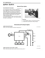
Tester knob indication
Continuity (
)
1
I831G1180011-02
2
I831G1180012-01
I831G1180013-01
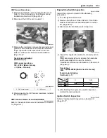
Bl/B
B/W
Color
Position
PUSH
I831G1180014-02
Содержание 2009 LT-A750XK9
Страница 2: ......
Страница 4: ......
Страница 5: ...SUPPLEMENTS L LT A750XK9 09 MODEL 10 LT A750XPK9 09 MODEL 11 ...
Страница 29: ...0A 15 General Information 99565 01010 013 CD ROM Ver 13 ...
Страница 57: ...0B 28 Maintenance and Lubrication 09915 40610 Oil filter wrench Page 0B 12 Page 0B 12 ...
Страница 68: ...0C 11 Service Data ...
Страница 310: ...1K 5 Exhaust System ...
Страница 482: ...4D 6 Parking Brake ...
Страница 528: ...6B 13 Steering Handlebar ...
Страница 555: ...Exterior Parts 9D 1 Body and Accessories Exterior Parts Repair Instructions Exterior Parts Construction B831G29406001 ...
Страница 581: ......
Страница 631: ...4A 6 Brake Control System and Diagnosis ...