28
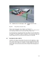
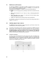
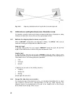
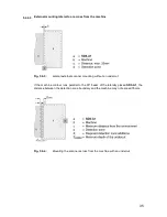
Fig. 5.2-4:
Opposing installation without height offset (crossed alignment)
5.3
Information on setting the dimensions of detection zones
The hazards caused by machines and systems place a wide range of demands on safety
distances and detection zones which must be appropriately defined.
5.3.1
With its
SD3SOFT
configuration and diagnostic software, the
SD3-A1
offers various
methods for setting the configurations of detection zones.
Numerical input
A separate dialog within the user program “
SD3SOFT
” allows the right, left and front
edges of the detection zone to be set using numerical values in mm.
Graphic input
A separate dialog within the user program “
SD3SOFT
” allows the basic contours of the
detection zone to be entered. The contours can be adapted infinitely to the desired size of
the detection zone. The following shapes are available:
In addition, the contours can be infinitely varied by:
partial segments as desired
5.3.2
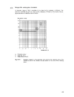
The maximum range of the detection zone S
MAX
4m (including the additions) for an object
with a diameter of 70mm and a reflectance factor of 1.8% (e.g. black corduroy). The
reference point of the measurement is the axis of the rotating mirror on the scanner
64mm behind the front edge of the scanner.
Methods of configuring detection zones using the PC
Range of the detection zone, resolution
x
circle
x
rectangle
x
polygon
x
changing
x
limiting and
x
deleting
Содержание SD3-A1
Страница 1: ......
Страница 12: ...12...
Страница 40: ...40 Fig 5 4 5 Considering the maximum measurement distance when safeguarding an area...
Страница 60: ...60 Fig 6 2 1 Example of a zone pair changeover for an AGV on a curved route...
Страница 61: ...61 Fig 6 2 2 Example of zone pair changeover with combined with reducing speed of the AGV...
Страница 101: ...101 13 13 Dimensional drawings of the SD3 A1...
Страница 102: ...102 13 14 Dimensional drawings of the mounting system...
Страница 106: ......

