26
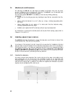
5.1 Attachment
and
dimensions
For attaching the
SD3-A1
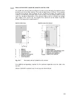
, four drill holes are located at the back of the unit. Any laser
scanner installation point is possible with mounting. The
SD3-A1
can, for example, also
be mounted on the head or inclined facing down.
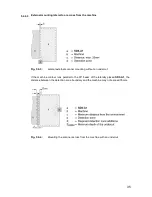
The mounting system
MS-SD3-1
is available as an accessory offering following
advantages:
For information on which parts and dimensions are required for mounting, please refer to
Chapter 13.13 and 13.14.
5.2
Installing adjacent laser scanners
The
SD3-A1
has been developed in a way that prevents several laser scanners from
interfering with one other as much as possible.
An increase in the response time can, however, be caused by the installation of several
adjacent laser scanners. If
none
of the constructive measures (section 5.2.1) described in
the following sections or the specific adjustment (section 5.2.2) are implemented,
then
the SD3-A1 response time set and shown in the configuration and diagnosis
software (SD3SOFT) is extended by 40ms.
This extension in the response time must
be taken into account when calculating the safety distance!
5.2.1 Constructive
measures
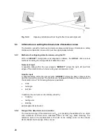
The direct external light irradiation from laser scanners of the same kind (905nm laser
light wavelength) in a line and at the same installation height can be prevented with
shielding plates at scan level. Shielding, as high as the scanner front screen and flush
with the front housing edge, is sufficient. The same also applies with installation in parallel
alignment and overlapping of the scan levels.
x
Speeds up the mounting process by providing screws that are accessible from the
front.
x
Allows vertical inclinations of up to 9°, either up or down, infinitely adjustable within
this range.
x
Allows lateral tilting of up to approx. 9° to either side from the midpoint setting,
infinitely adjustable within this range.
x
Enables quick replacement of the scanner without requiring realignment.
Содержание SD3-A1
Страница 1: ......
Страница 12: ...12...
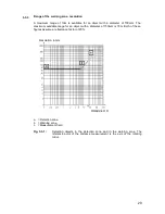
Страница 40: ...40 Fig 5 4 5 Considering the maximum measurement distance when safeguarding an area...
Страница 60: ...60 Fig 6 2 1 Example of a zone pair changeover for an AGV on a curved route...
Страница 61: ...61 Fig 6 2 2 Example of zone pair changeover with combined with reducing speed of the AGV...
Страница 101: ...101 13 13 Dimensional drawings of the SD3 A1...
Страница 102: ...102 13 14 Dimensional drawings of the mounting system...
Страница 106: ......

