95
12.3
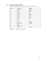
Coding of the control cable X1
The following table defines the pin assignments for the 15-pin connector cable
Table 12.3-1:
Coding of the control cable X1
Pin No.
Color code
Meaning
1 Black
GND
2 Blue
Restart
3 Red
U
B
4 Orange
FP
1
5 Yellow
Alarm
1
6 Green
FP
2
7 Violet
FP
3
8 Gray
FP
4
9 N.C.
10 N.C.
11 White
OSSD
1
12
White / Black
OSSD 2
13 N.C.
14
White / Brown
15 Brown
Alarm
2
Содержание SD3-A1
Страница 1: ......
Страница 12: ...12...
Страница 40: ...40 Fig 5 4 5 Considering the maximum measurement distance when safeguarding an area...
Страница 60: ...60 Fig 6 2 1 Example of a zone pair changeover for an AGV on a curved route...
Страница 61: ...61 Fig 6 2 2 Example of zone pair changeover with combined with reducing speed of the AGV...
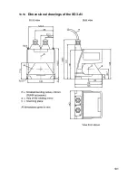
Страница 101: ...101 13 13 Dimensional drawings of the SD3 A1...
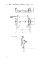
Страница 102: ...102 13 14 Dimensional drawings of the mounting system...
Страница 106: ......

