63
7.3 Alarm
1
(X1-5)
As long as the output X1-5 is switched ON, the system signals trouble-free operation.
If it is switched OFF, the following states are reported:
Both the reporting of a warning zone interruption and the signaling of the warning and
error state can be selected either separately or in combination. This procedure is
described in the instruction manual (software operation) for the program “
SD3SOFT
”.
Output X1-5 is equipped with an internal electronic current limit to protect it against
damage from overload.
7.4 Alarm
2
(X1-15)
As long as the output X1-15 is switched ON, the system signals trouble-free operation.
If it is switched OFF, the following states are reported:
Output X1-15 is equipped with an internal electronic current limit to protect it against
damage from overload.
x
Interruption of the warning zone is shown by the continuously lit LED 2 in the
indicator field of the scanner.
x
Warning state:
For instance, the system may detect a slight dirt buildup on the optical window. To
signal this state, LED 5 on the scanner flashes (2Hz). The user should clean the
optical window before it gets dirtier; waiting too long will cause a device error to be
reported and the outputs OSSD 1 and OSSD 2 to be switched OFF.
x
Device error:
Such as an erroneous reference measurement or extreme dirt buildup on the optical
window. This state is signaled by LED 5 flashing quickly (4Hz).
x
Warning state:
For instance, the system may detect a slight dirt buildup on the optical window. To
signal this state, LED 5 on the scanner flashes (2Hz). The user should clean the
optical window before it gets dirtier; waiting too long will cause a device error to be
reported and the outputs OSSD 1 and OSSD 2 to be switched OFF.
x
Device error:
Such as an erroneous reference measurement or extreme dirt buildup on the optical
window. This state is signaled by LED 5 flashing quickly (4Hz).
Содержание SD3-A1
Страница 1: ......
Страница 12: ...12...
Страница 40: ...40 Fig 5 4 5 Considering the maximum measurement distance when safeguarding an area...
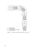
Страница 60: ...60 Fig 6 2 1 Example of a zone pair changeover for an AGV on a curved route...
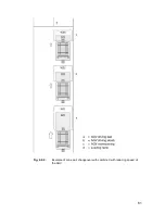
Страница 61: ...61 Fig 6 2 2 Example of zone pair changeover with combined with reducing speed of the AGV...
Страница 101: ...101 13 13 Dimensional drawings of the SD3 A1...
Страница 102: ...102 13 14 Dimensional drawings of the mounting system...
Страница 106: ......

