Medium Optical Disk (RW551/RW552) Library
5–10
EK–MOL80–SV. B01
6.
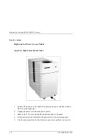
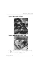
Disconnect the control panel power cable located at the upper left outside
corner (rear access).
CAUTION
In the next step, lift straight up to allow the control
panel assembly to clear the jukebox chassis.
7.
From the right end lift up the front right panel. Spread the bottom front and
rear a bit while lifting up and tilting off.
Reassembly
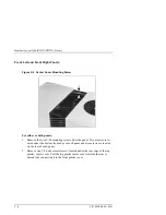
When replacing the front right panel be sure to put the control panel ribbon ca-
ble under the cable clamp on the frame. If the cable is not held in place by the
cable clamp it may become entangled with the mailslot assembly.
For the left front panel
1.
From the left end lift up the front left panel.
2. Spread the bottom front and rear a bit while lifting up and tilting off.
Содержание RW551
Страница 27: ...Medium Optical Disk RW551 RW552 Library 3 2 EK MOL80 SV B01 Figure 3 2 Rear Panel SCSI Connect...
Страница 34: ...Chapter 3 Product Configuration and Operation EK MOL80 SV B01 3 9 Figure 3 4 Control Panel Menu Tree...
Страница 92: ...end...
Страница 139: ...Chapter 5 Removal and Replacement EK MOL80 SV B01 5 47 Figure 5 49 Jukebox Exploded View 1 of 2...
Страница 140: ...Medium Optical Disk RW551 RW552 Library 5 48 EK MOL80 SV B01 Figure 5 49 Jukebox Exploded View 2 of 2...
Страница 141: ...Chapter 5 Removal and Replacement EK MOL80 SV B01 5 49 Figure 5 50 Jukebox Power Harness...
Страница 142: ...Medium Optical Disk RW551 RW552 Library 5 50 EK MOL80 SV B01 Figure 5 51 Jukebox Pulley and Rope Diagram...
Страница 166: ...Chapter 6 Theory of Operation EK MOL80 SV B01 6 23 Figure 6 10 User Zone Layout for 1 3 Gbyte Media g 1...
Страница 167: ...Medium Optical Disk RW551 RW552 Library 6 24 EK MOL80 SV B01 Figure 6 11 User Zone Layout for 1 3 Gbyte g 16...
Страница 168: ...Chapter 6 Theory of Operation EK MOL80 SV B01 6 25 Figure 6 12 User Zone Layout for 2 6 Gbyte Media 1 024 bytes sector...


