Chapter 6. Theory of Operation
EK–MOL80–SV. B01
6–5
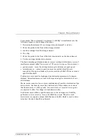
The processor interface functions are: decoding the processor's address space,
and generating select and strobe signals to give the processor access to the flash
EEPROM, RAM, the SCSI controller, internal registers, I/O ports, and optional
external registers. Also, the processor interface function of the chip includes the
handling of internally- and externally-generated interrupt sources.
The programmable features section of the chip provides a control panel display
state machine and firmware-configurable feature and general-purpose ports.
The servo system section of the chip provides servo timers, three motor control
pulse-width modulators, and three quadrature encoder channels.
The General Purpose Bus is controlled by the ASIC. This bus provides access to
registers located on other PCAs. This bus is primarily used for the drive
interface.
Drive interface signals EJECT and BUSY are also handled by this chip.
The ASIC is also the interface between the processor and the motors. The ASIC
monitors the position encoders and uses that information to increment or
decrement counters on the chip. The ASIC also provides pulse width modulation
(PWM) output signals to drive the motor circuitry.
All SCSI signals are handled by the NCR 53C80 chip under control of the
MC68EC000 processor and the Autochanger ASIC chip.
FLASH EEPROM— The controller firmware resides in two flash EEPROMs.
These flash EEPROMs allow new firmware versions to be downloaded to the
controller in the field.
RAM— The two RAM chips are special, low-power CMOS static RAMs. A
standby capacitor on the PCA takes over powering these chips if main power is
lost. The chips remain in standby mode (from about 10 to 60 days), providing a
non-volatile memory storage capability when the unit is powered off.
The X,Y, and Z MOTOR CONTROL DRIVERS take the pulse-width modulated
signals from the motor control chip and change them into power signals for the
translate, vertical, and plunge motors.
Motor position is by returned through the vertical umbilical cable. The translate
motor position is determined by a photomicro sensor on the picker PCA. The
plunge motor position is determined by an optical encoder mounted on the motor
itself. The vertical position is determined by an optical strip encoder located on
the translate frame.
The CONTROL PANEL INTERFACE provides a serial data interface and power
for the display.
Содержание RW551
Страница 27: ...Medium Optical Disk RW551 RW552 Library 3 2 EK MOL80 SV B01 Figure 3 2 Rear Panel SCSI Connect...
Страница 34: ...Chapter 3 Product Configuration and Operation EK MOL80 SV B01 3 9 Figure 3 4 Control Panel Menu Tree...
Страница 92: ...end...
Страница 139: ...Chapter 5 Removal and Replacement EK MOL80 SV B01 5 47 Figure 5 49 Jukebox Exploded View 1 of 2...
Страница 140: ...Medium Optical Disk RW551 RW552 Library 5 48 EK MOL80 SV B01 Figure 5 49 Jukebox Exploded View 2 of 2...
Страница 141: ...Chapter 5 Removal and Replacement EK MOL80 SV B01 5 49 Figure 5 50 Jukebox Power Harness...
Страница 142: ...Medium Optical Disk RW551 RW552 Library 5 50 EK MOL80 SV B01 Figure 5 51 Jukebox Pulley and Rope Diagram...
Страница 166: ...Chapter 6 Theory of Operation EK MOL80 SV B01 6 23 Figure 6 10 User Zone Layout for 1 3 Gbyte Media g 1...
Страница 167: ...Medium Optical Disk RW551 RW552 Library 6 24 EK MOL80 SV B01 Figure 6 11 User Zone Layout for 1 3 Gbyte g 16...
Страница 168: ...Chapter 6 Theory of Operation EK MOL80 SV B01 6 25 Figure 6 12 User Zone Layout for 2 6 Gbyte Media 1 024 bytes sector...


