Chapter 5. Removal and Replacement
EK–MOL80–SV. B01
5–29
2.
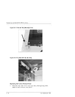
Disconnect the two power cables to the vertical motor. Note the orientation
of the motor and its cable connections with respect to the gear box
(for reassembly).
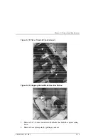
Figure 5–33 Vertical Motion Motor
3.
Remove two T-15 motor mounting screws on the gear box.
Reassembly:
When replacing the motor, use the orienting pegs on the motor to place it cor-
rectly on the gear box.
Содержание RW551
Страница 27: ...Medium Optical Disk RW551 RW552 Library 3 2 EK MOL80 SV B01 Figure 3 2 Rear Panel SCSI Connect...
Страница 34: ...Chapter 3 Product Configuration and Operation EK MOL80 SV B01 3 9 Figure 3 4 Control Panel Menu Tree...
Страница 92: ...end...
Страница 139: ...Chapter 5 Removal and Replacement EK MOL80 SV B01 5 47 Figure 5 49 Jukebox Exploded View 1 of 2...
Страница 140: ...Medium Optical Disk RW551 RW552 Library 5 48 EK MOL80 SV B01 Figure 5 49 Jukebox Exploded View 2 of 2...
Страница 141: ...Chapter 5 Removal and Replacement EK MOL80 SV B01 5 49 Figure 5 50 Jukebox Power Harness...
Страница 142: ...Medium Optical Disk RW551 RW552 Library 5 50 EK MOL80 SV B01 Figure 5 51 Jukebox Pulley and Rope Diagram...
Страница 166: ...Chapter 6 Theory of Operation EK MOL80 SV B01 6 23 Figure 6 10 User Zone Layout for 1 3 Gbyte Media g 1...
Страница 167: ...Medium Optical Disk RW551 RW552 Library 6 24 EK MOL80 SV B01 Figure 6 11 User Zone Layout for 1 3 Gbyte g 16...
Страница 168: ...Chapter 6 Theory of Operation EK MOL80 SV B01 6 25 Figure 6 12 User Zone Layout for 2 6 Gbyte Media 1 024 bytes sector...


