Medium Optical Disk (RW551/RW552) Library
6–4
EK–MOL80–SV. B01
The Autochanger Controller PCA
The autochanger controller PCA contains the following major components:
•
microprocessor
•
autochanger ASIC
•
NCR 53C80 Chip (SCSI bus control)
•
flash EEPROM
•
RAM
•
SCSI interface
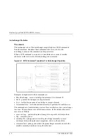
Figure 6–2 Autochanger Controller PCA Block Diagram
The MICROPROCESSOR is a Motorola MC68EC000 running at 12.288 MHz.
This microprocessor controls all processes on the controller PCA such as servos,
SCSI interface, and commands to the control panel.
Associated with the microprocessor is clocking circuitry, RAM with standby
power supplied by a capacitor, and ROM.
The AUTOCHANGER APPLICATION-SPECIFIC INTEGRATED CIRCUIT
(ASIC) provides the processor interface, programmable features, and a servo
system.
Содержание RW551
Страница 27: ...Medium Optical Disk RW551 RW552 Library 3 2 EK MOL80 SV B01 Figure 3 2 Rear Panel SCSI Connect...
Страница 34: ...Chapter 3 Product Configuration and Operation EK MOL80 SV B01 3 9 Figure 3 4 Control Panel Menu Tree...
Страница 92: ...end...
Страница 139: ...Chapter 5 Removal and Replacement EK MOL80 SV B01 5 47 Figure 5 49 Jukebox Exploded View 1 of 2...
Страница 140: ...Medium Optical Disk RW551 RW552 Library 5 48 EK MOL80 SV B01 Figure 5 49 Jukebox Exploded View 2 of 2...
Страница 141: ...Chapter 5 Removal and Replacement EK MOL80 SV B01 5 49 Figure 5 50 Jukebox Power Harness...
Страница 142: ...Medium Optical Disk RW551 RW552 Library 5 50 EK MOL80 SV B01 Figure 5 51 Jukebox Pulley and Rope Diagram...
Страница 166: ...Chapter 6 Theory of Operation EK MOL80 SV B01 6 23 Figure 6 10 User Zone Layout for 1 3 Gbyte Media g 1...
Страница 167: ...Medium Optical Disk RW551 RW552 Library 6 24 EK MOL80 SV B01 Figure 6 11 User Zone Layout for 1 3 Gbyte g 16...
Страница 168: ...Chapter 6 Theory of Operation EK MOL80 SV B01 6 25 Figure 6 12 User Zone Layout for 2 6 Gbyte Media 1 024 bytes sector...


