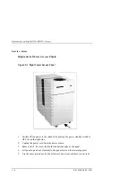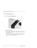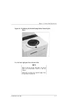
Chapter 5. Removal and Replacement
EK–MOL80–SV. B01
5–17
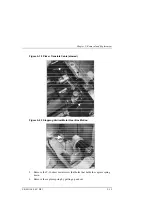
Figure 5–16 Cooling Fans
Replacing the Picker
1.
Follow the steps in the service access procedure at the beginning of this
chapter to remove the right access panel, rear access-panel and front right
panel.
2.
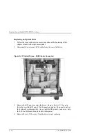
Unplug the picker umbilical cable.
To detach the cable, grab the tab on the
end of the cable and pull.
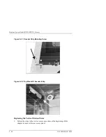
Figure 5–17 Picker Umbilical Cable
Содержание RW551
Страница 27: ...Medium Optical Disk RW551 RW552 Library 3 2 EK MOL80 SV B01 Figure 3 2 Rear Panel SCSI Connect...
Страница 34: ...Chapter 3 Product Configuration and Operation EK MOL80 SV B01 3 9 Figure 3 4 Control Panel Menu Tree...
Страница 92: ...end...
Страница 139: ...Chapter 5 Removal and Replacement EK MOL80 SV B01 5 47 Figure 5 49 Jukebox Exploded View 1 of 2...
Страница 140: ...Medium Optical Disk RW551 RW552 Library 5 48 EK MOL80 SV B01 Figure 5 49 Jukebox Exploded View 2 of 2...
Страница 141: ...Chapter 5 Removal and Replacement EK MOL80 SV B01 5 49 Figure 5 50 Jukebox Power Harness...
Страница 142: ...Medium Optical Disk RW551 RW552 Library 5 50 EK MOL80 SV B01 Figure 5 51 Jukebox Pulley and Rope Diagram...
Страница 166: ...Chapter 6 Theory of Operation EK MOL80 SV B01 6 23 Figure 6 10 User Zone Layout for 1 3 Gbyte Media g 1...
Страница 167: ...Medium Optical Disk RW551 RW552 Library 6 24 EK MOL80 SV B01 Figure 6 11 User Zone Layout for 1 3 Gbyte g 16...
Страница 168: ...Chapter 6 Theory of Operation EK MOL80 SV B01 6 25 Figure 6 12 User Zone Layout for 2 6 Gbyte Media 1 024 bytes sector...


