Medium Optical Disk (RW551/RW552) Library
5–6
EK–MOL80–SV. B01
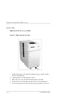
Front Left and Front Right Panels:
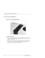
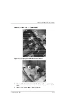
Figure 5–3 Center Cover Mounting Screw
For either or both panels:
1. Remove the four T-20 mounting screws from the panel. Two screws are lo-
cated under the bottom front edge of each panel and two screws are located
on the rear of each panel.
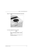
2. Remove one T-20, sheet metal screw located under the rear edge of the top,
plastic, center cover. Pull the top plastic center cover towards the rear to
unlock tabs connecting it to the front plastic cover.
Содержание RW551
Страница 27: ...Medium Optical Disk RW551 RW552 Library 3 2 EK MOL80 SV B01 Figure 3 2 Rear Panel SCSI Connect...
Страница 34: ...Chapter 3 Product Configuration and Operation EK MOL80 SV B01 3 9 Figure 3 4 Control Panel Menu Tree...
Страница 92: ...end...
Страница 139: ...Chapter 5 Removal and Replacement EK MOL80 SV B01 5 47 Figure 5 49 Jukebox Exploded View 1 of 2...
Страница 140: ...Medium Optical Disk RW551 RW552 Library 5 48 EK MOL80 SV B01 Figure 5 49 Jukebox Exploded View 2 of 2...
Страница 141: ...Chapter 5 Removal and Replacement EK MOL80 SV B01 5 49 Figure 5 50 Jukebox Power Harness...
Страница 142: ...Medium Optical Disk RW551 RW552 Library 5 50 EK MOL80 SV B01 Figure 5 51 Jukebox Pulley and Rope Diagram...
Страница 166: ...Chapter 6 Theory of Operation EK MOL80 SV B01 6 23 Figure 6 10 User Zone Layout for 1 3 Gbyte Media g 1...
Страница 167: ...Medium Optical Disk RW551 RW552 Library 6 24 EK MOL80 SV B01 Figure 6 11 User Zone Layout for 1 3 Gbyte g 16...
Страница 168: ...Chapter 6 Theory of Operation EK MOL80 SV B01 6 25 Figure 6 12 User Zone Layout for 2 6 Gbyte Media 1 024 bytes sector...


