background image

AC Power Distribution Unit

4-6

Fifth Edition

95897


Removal

1. Review the information under 

“Before Beginning” on page 4-2

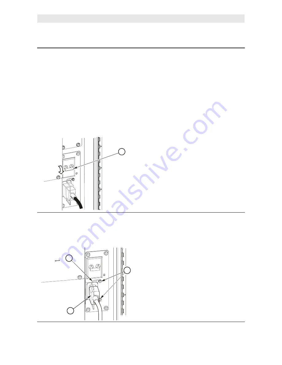
2. Remove power from the library by pressing down on the power switch. 

WARNING:
Electrocution hazard:
 Make sure you press down on the power switch before 
removing the PDU.

WARNUNG: Lebensgefährliche Spannung! Bevor Sie den Netzstrom-Verteiler 
herausnehmen, kippen Sie den Netzschalter nach unten. 

Avertissement:
Danger d'électrocution:
 Appuyer sur le commutateur avant de retirer l'unité de 
distribution de l'énergie (PDU).

1. Power switch

3. Use a T-15 Torx bit to remove the two screws holding the strain relief in place.

4. Remove the strain relief from the power cable.

5. Disconnect the external power cable.

1. Strain relief
2. External power cable
3. Screws

E67159

1

C67197

1

2

3

Содержание L180

Страница 1: ...L180 Tape Library Service Manual Document 95897...

Страница 2: ......

Страница 3: ...L180 Tape Library Service Manual...

Страница 4: ...arks of Storage Technology Corporation Other product names features and terms used in this publication are for informational purposes only and might be trademarks of Storage Technology Corporation or...

Страница 5: ...rmation screen shots and procedures in Chapter 2 Operator Panel with Chapter 3 Firmware Operation Changed the title to Chapter 2 Configuration Moved the information in Chapter 4 Remote Setup to the In...

Страница 6: ...Summary of Changes iv Fifth Edition 95897 This page intentionally left blank...

Страница 7: ...Documents on CD xx Hardcopy Publications xx Safety xxi Safety Precautions xxi Lifting Techniques xxii Shoulder Elbow Wrist and Hand Safety xxii Electrostatic Discharge Damage Prevention xxiii ESD Pre...

Страница 8: ...ry Information 2 8 Setting the Library SCSI ID 2 8 Setting the Library Fibre Channel Port 0 Address 2 10 Enabling Disabling Fast Load 2 11 Setting the Date 2 12 Setting the Time 2 13 Drive Configurati...

Страница 9: ...al Problems and Causes 3 17 Diagnostic Tests 3 19 Diagnostics Menu 3 19 Get Put Loop Diagnostic Test 3 20 Mount Dismount Loop Diagnostic Test 3 21 Other Diagnostic Tests 3 22 Placing the Library Onlin...

Страница 10: ...l 4 77 Replacement 4 80 Z Flex Cable 4 84 Removal 4 85 Replacement 4 87 Library SCSI Cable 4 90 Preparation 4 90 Removal 4 91 Replacement 4 93 Drive SCSI Y Cable 4 95 Drive Preparation 4 95 Removal 4...

Страница 11: ...wer Supply A 6 Drive Column Power A 8 Drive Column Single Power Cable A 8 Drive Column Two Power Cables A 8 Drive Column Power Connections A 8 Cooling A 9 Optional Cooling Fans A 9 Robot A 10 Theta As...

Страница 12: ...lic Arbitrated Loop A 21 Fibre Channel Cable Considerations A 21 HBA Requirements A 22 L Series Library Admin A 22 Internal Interfaces A 23 Client to CAP A 23 Library to HVD or Single Ended SCSI Clien...

Страница 13: ...SCSI Interface Configuration Menu 2 8 Figure 2 6 Library Fibre Channel Interface Configuration Menu 2 10 Figure 2 7 Drive Configuration Menu 2 14 Figure 2 8 Network Configuration Menu 2 18 Figure 2 9...

Страница 14: ...9 HP Ultrium Drive 4 124 Figure 4 20 Seagate Ultrium Drive 4 130 Figure A 1 Library Block Diagram A 1 Figure A 2 UPS Cable Diagram A 6 Figure A 3 Robotic Components A 10 Figure A 4 Hand Camera Assembl...

Страница 15: ...6 Table A 1 DC Power Supply Specifications A 2 Table A 2 Library Power Specifications A 3 Table A 3 Library Power Cables A 4 Table A 4 Maximum Number of Drives on a Single 220 VAC Circuit A 5 Table A...

Страница 16: ...Tables xiv Fifth Edition 95897 This page intentionally left blank...

Страница 17: ...the following information Chapter 1 Introduction contains an introduction for servicing the L180 Tape Library and the basic components in it Chapter 2 Configuration provides information about how to u...

Страница 18: ...njury or death A warning always precedes the information to which it pertains Conventions Naming conventions found in this publication for the L180 Tape Library include L180 library and tape library N...

Страница 19: ...Positions for circuit breakers jumpers and switches ON Default font capitalization follows label on product otherwise all uppercase Screen text including screen captures screen messages and user input...

Страница 20: ...pe System Product Manual Available from Quantum 81 60118 0x Super DLT 220 Product Manual Available from Quantum 81 80000 0x Ultrium Tape Drive Publications Part Number 3580 IBM Ultrium Tape Drive Setu...

Страница 21: ...onic Documentation Center CRC membership entitles you to other proactive services such as HIPER subscriptions technical tips answers to frequently asked questions and online product support contact in...

Страница 22: ...lications Contact your local Customer Services Logistics Depot to order this CD and to get onto the distribution list for this CD The Documents on CD is only for StorageTek employees Hardcopy Publicat...

Страница 23: ...rs and supplies Power off the equipment that is being serviced before you remove a field replaceable unit FRU or other component Remember that dangerous voltages could still be present in some areas e...

Страница 24: ...you lean forward Whenever you can grip the load with your whole hand and use two hands Carry objects at elbow height and close to your body The farther away you hold an object the more force it puts o...

Страница 25: ...are servicing StorageTek equipment or handling ESD sensitive components ESD Precautions Always take the following general precautions when you work with ESD sensitive components Wear ESD protection w...

Страница 26: ...step 3 Slip on an ESD wrist strap Make sure that the strap is comfortable and makes contact with the entire circumference of your wrist 4 Snap one end of the coil cord to the wrist band Access the Equ...

Страница 27: ...rary If the front door is opened an electrical interlock removes power from the robot assembly Behind the front door covers are placed over the MPC card the AC power supply and the DC power supply to...

Страница 28: ...e do not block library or drive exhaust areas the electronic module exhaust area perforated metal or other similar ventilation Locate the equipment so that the library doors adequately clear the equip...

Страница 29: ...500 525 550 600 575 59 F 0 89 6 F 0 L180 Recommendations for Equipment Rated to 35 C Room Ambient Temperature C 0 0 Rack Equipment Power Watts Fan Recommended 32 31 30 29 28 27 26 25 24 23 20 19 18 1...

Страница 30: ...StorageTek Fibre Channel equipment contains a laser transceiver that is a Class 1 Laser Product Each laser transceiver has an output of less than 70 W and a wavelength of 850 nm StorageTek s Class 1...

Страница 31: ...r or a laser transceiver module Hazardous conditions might exist from laser power levels that are capable of causing injury to the eye Be especially careful when using optical instruments with this eq...

Страница 32: ...dule Hazardous conditions might exist from laser power levels that are capable of causing injury to the eye Be especially careful when using optical instruments with this equipment Such instruments mi...

Страница 33: ...ents that you need to service the library Figure 1 1 Service Clearances C67109 1 2 6 m 8 5 ft 2 0 8 m 2 6 ft 3 At all times make sure at least 51 mm 2 in exists on the right and left sides of the libr...

Страница 34: ...reakers In addition the standard PDU supplies AC voltage to the drive column A second optional PDU can supply power for redundancy DC Power Supplies If the library has two DC power supplies one supply...

Страница 35: ...ing your fingers in the slot and pulling the door open The door swings open to the right 2 Find the power switch near the bottom of the library shown in Figure 1 3 3 Power on the library by lifting up...

Страница 36: ...cell arrays that each hold six cartridges The cell arrays are stacked in columns and the columns are arranged around the robot Note The top two cells in each column are reserved and not available Six...

Страница 37: ...fth Edition 1 5 Component Overview Figure 1 4 Major Components C67104 1 Rear door 2 Rack door 3 Operator panel 4 Front door 5 Cartridge access port CAP 6 Robotics 7 Arrays 8 Tape drives C67104 1 2 3 6...

Страница 38: ...Component Overview 1 6 Fifth Edition 95897 Figure 1 5 Electronics Module Components C67106 1 Electronics Module 2 MPC card 3 CPCI card cage assembly 4 MPU or MPW card 5 MPV card C67106 1 2 3 4 5...

Страница 39: ...cut away 7 Main AC power distribution unit PDU 2 View from library rear 8 Optional AC PDU 3 MPC card enclosed 9 Power switches circuit breakers 4 Fan tray assembly 10 Library to client SCSI I O conne...

Страница 40: ...4 Reserved cell array 5 Drive column 6 140 storage cell configuration 7 174 storage cell configuration 8 Blocked storage cells no cartridges allowed 9 Swap cell leave empty C67107 8 7 9 3 2 1 PANEL 1...

Страница 41: ...he robot has a cartridge in the hand When power is restored the robot automatically inserts this cartridge into this cell as part of the initialization sequence To install diagnostic and cleaning cart...

Страница 42: ...1 8 2 7 3 5 4 4 5 2 6 1 Figure 1 9 Tape Drives C67052 1 DLT or Ultrium drive only in the top most slot 2 Two 9840 T9840 drives shown space equivalent to three DLT or Ultrium drives 3 Three DLT drives...

Страница 43: ...the CAP door is open 4 CAP button opens and closes the CAP 5 MENU button 6 Arrow down button moves the cursor down and decrements a value highlighted on the screen 7 SELECT button selects an item save...

Страница 44: ...Component Overview 1 12 Fifth Edition 95897 This page intentionally left blank...

Страница 45: ...rades you can download microcode from the multi platform support web site at http mpss stortek com This Web site lists the Automated Tape Solutions Library Drive Matrix along with the product list tap...

Страница 46: ...in flash97 release prm CAUTION Equipment Damage Do not attempt to do perform any operations on the personal computer or library until the operator panel displays DOWNLOAD COMPLETE Damage to the MPC p...

Страница 47: ...Hyperterminal session b For WIN2000 machines go to Start Programs Accessories Communications Hyperterminal and open a Hyperterminal session 4 Within the File Properties configure the connection as fo...

Страница 48: ...the following prompt Reboot yes Respond with yes to reboot the machine and activate the microcode Or you may power cycle or IPL the library to activate the microcode If you do not reboot power cycle...

Страница 49: ...ion procedure 1 Read the information in this chapter 2 Determine your choices and write your configuration information into Table 2 2 and Table 2 3 on page 2 7 3 Make a copy of this information and ke...

Страница 50: ...ersonality and input a password for a Web interface product 5 Select the configuration menu for the device you want to configure Figure 2 3 shows an example of the main configuration screen CAUTION Po...

Страница 51: ...ddress Library capacity Automatically configured during IPL Library name Library SCSI ID Library Worldwide ID Not configurable pre set at the factory Network gateway address Port 0 Address library Por...

Страница 52: ...o save a revised library SCSI ID or Fibre Channel address you must reset the library by pressing the RESET button Setting the Library SCSI ID The Lib SCSI I F Config Menu lets you view the library s S...

Страница 53: ...p with LIBRARY CONFIG 4 Press the SELECT button The Lib Config Menu will appear The cursor will line up with LIB SCSI I F CONFIG 5 Press the SELECT button The Lib SCSI I F Config Menu will appear This...

Страница 54: ...n Menu will appear The cursor will line up with LIBRARY CONFIG 4 Press the SELECT button The Lib Config Menu will appear The cursor will line up with LIB FIBRE I F CONFIG 5 Press the SELECT button The...

Страница 55: ...Pressing the SELECT button to save the address If the library Fibre Channel Port 0 address is the only configuration value you wish to set at this time press the RESET button If you wish to set other...

Страница 56: ...nu press an arrow button until the cursor underscores DATE 2 Press the SELECT button An editing screen appears 3 On the editing screen a Use the up and down arrow buttons to select a value for each po...

Страница 57: ...NU button to move left to the previous field 3 When the screen displays your desired setting press the SELECT button from the right most field to save the changes Press the MENU button to abort If you...

Страница 58: ...ate whether the drive is on the same SCSI bus as the library or off the SCSI bus Notes These statements apply to this menu 1 The cursor position is saved on all screens that list the library s drives...

Страница 59: ...bus means that the drive is not on the same SCSI bus You set the drive SCSI IDs and bus status choices from the drive configuration menu You can enter both values for each drive at the same time To s...

Страница 60: ...use the down arrow button to scroll to drives 08 and 09 2 Use the up and down arrow buttons to change the ID 3 When the ID is correct press SELECT to save your changes A message screen will appear to...

Страница 61: ...to 0 If you select disabled the address will arbitrate through the channel 3 Press the SELECT button to save the changes Press the MENU button to abort 4 If you wish to set other configuration values...

Страница 62: ...consult the systems administrator for some information Viewing the Ethernet Address Note The library s Ethernet address is pre set at the factory You cannot change it To view the Ethernet address 1 A...

Страница 63: ...red setting press the SELECT button twice to save the changes Press the MENU button to abort Setting the IP Address The system administrator might assign the library an IP address which makes the libr...

Страница 64: ...t to the previous field 4 When the screen displays your desired setting press the SELECT button from the right most field to save the changes Press the MENU button to abort Setting the Subnet Mask Add...

Страница 65: ...our library has StorageTek s L Series Library Administrator installed you must set a web password at the operator panel For instructions on how to set this value see the documentation that shipped wit...

Страница 66: ...e a limited life span After multiple uses a cleaning cartridge must be replaced and disposed of If you have enabled the Auto Clean feature you can use the operator panel to set the maximum number of t...

Страница 67: ...s correct press the SELECT button to save the changes Press the MENU button to abort 8 When you are finished press the MENU button twice to return to the library status screen L Series Library Admin E...

Страница 68: ...Configuration Overview 2 24 Fifth Edition 95897 This page intentionally left blank...

Страница 69: ...s TIP 2000 DC Power Problems on page 3 8 TIP 3000 Operator Panel on page 3 10 TIP 4000 Interface on page 3 11 TIP 5000 Tape Drives on page 3 13 also see Table 3 2 on page 3 16 for drive messages and T...

Страница 70: ...er problem Yes Go to TIP 1000 AC Power Problems on page 3 3 No Go to step 2 2 Do you have an DC power problem Yes Go to TIP 2000 DC Power Problems on page 3 8 No Go to step 3 3 Do you have an operator...

Страница 71: ...tep 3 No Reseat the power cord 3 Power off all the tape drives 4 Lift the PDU breaker Does it trip Yes Go to step 5 No Power on drives one at a time to see which drive causes the breaker to trip Repla...

Страница 72: ...voltage in the next procedure WARNUNG Bevor Sie die Netzspannung wie nachstehend beschrieben messen treffen Sie die entsprechenden Sicherheitsma nahmen Avertissement Danger d lectrocution Avant de me...

Страница 73: ...nutes before the UPS will shutdown WARNING Make sure you follow the procedures in Safety on page xxi Problem Conditions That Could Cause This Problem No power to the library Defective UPS switch or po...

Страница 74: ...the UPS with a table lamp If the light is very dim check the input voltage Battery not connected properly Check the battery connections UPS will not turn off Internal UPS fault Do not attempt to use...

Страница 75: ...hutdown by remote control None The UPS will restart automatically when power is restored All indicators are lit and the UPS emits a constant beeping sound Internal UPS fault Do not use the UPS Turn th...

Страница 76: ...the breaker trip Yes Go to TIP 1000 AC Power Problems on page 3 3 No Go to step 4 4 Look at the small viewing window on the DC power supply Is the green LED lit Yes Go to step 6 No Turn off the breake...

Страница 77: ...the drive area working Yes Go to step 7 No 43 VDC is missing Replace the DC power supply 7 Is the operator panel lit Yes Go to step 8 No Replace in this order 1 Operator card MPO 2 Operator panel cabl...

Страница 78: ...customer place the library and tape drives offline 2 Open the rear door 3 Is the PDU breaker on Yes Go to step 5 No Lift the breaker Go to step 4 4 Does the breaker trip Yes Go to TIP 1000 AC Power Pr...

Страница 79: ...ther single ended or differential If the screen displays Invalid you have mixed single ended devices with differential devices somewhere on the bus Correct the bus connection then use the menu to veri...

Страница 80: ...od Yes Go to step 9 No Re seat the cable connector or correct the cable type 9 Check the SCSI terminator at the client Is the terminator turned on Yes Go to step 10 No Turn it on 10 Is the length of t...

Страница 81: ...are reported in this menu as Not connected Unknown drive Not communicating Not functional Not loadable Problem Conditions That Could Cause This Problem The client system Cannot access a drive Marks t...

Страница 82: ...Yes The drive s Tape Transport Interface TTI connector is not firmly connected or the AC switch may be off See steps 4 and 5 No Go to step 9 8 Check the host to drive cable connection at the library...

Страница 83: ...rive configuration options The library will automatically assign the same address to the replacement drive However you may need to configure other information for the drive before performing the swap...

Страница 84: ...ith the library This drive might be powered off NOT FUNCTIONAL This drive is not operating properly EMPTY No cartridge is loaded in this drive CARTRIDGE IN This drive contains a cartridge but it is no...

Страница 85: ...ot set correctly Bad bridge if on a network Clean me light is on You clean the drive and light comes back on What is the light really telling you Possible read write errors Bad tapes or drive is getti...

Страница 86: ...Try again Re IPL the library Unload all drives from the operating systems first Try again Restart application Try again Re IPL the host Customer reports drive keeps going down Watch the amount of tim...

Страница 87: ...Diagnostics Menu lets you perform these functions Drive related functions Clean Drive Enables you to clean tape drives manually Mount Inserts a test cartridge into a drive Dismount Removes a test cart...

Страница 88: ...Make sure a diagnostic cartridge is in the reserved area 4 From the status screen press the MENU button 5 Use the down arrow button to move the cursor next to DIAGNOSTICS 6 Press the SELECT button The...

Страница 89: ...m the status screen press the MENU button The main menu appears 5 Use the down arrow button to move the cursor next to DIAGNOSTICS 6 Press the SELECT button The diagnostics screen appears 7 Use the do...

Страница 90: ...to load the audit data to client memory Clean Drive This routine will mount and dismount a specified cleaning cartridge to a drive This routine does not require the library to be offline Make sure yo...

Страница 91: ...ge 4 35 MPC Card on page 4 39 MPU Card on page 4 49 MPW Card on page 4 53 MPV Card on page 4 56 Theta Motor on page 4 65 Z Motor on page 4 76 Z Flex Cable on page 4 84 Library SCSI Cable on page 4 90...

Страница 92: ...bit 1 4 20 requires a Torx T 30 bit 4 40 pan head requires a Torx T 10 bit 4 40 flathead requires a Torx T 09 bit Before Beginning Read the safety and ESD instructions in Safety on page xxi If removin...

Страница 93: ...ended all jobs to that drive 2 Open the library rear door by pulling gently on the finger slot 3 Remove power from the library by pressing down on the power switch on the bottom left area of the libr...

Страница 94: ...e left side of the door If you are replacing the other FRUs Open the rear door by pulling gently on the finger slot as shown in step 2 If you are replacing the theta motor tape drive or drive SCSI Y c...

Страница 95: ...wer distribution unit Note If the library has two AC PDUs this field replaceable unit may be removed and replaced while the library is powered on Note See TIP 1010 UPS Power Problems on page 3 5 for i...

Страница 96: ...NUNG Lebensgef hrliche Spannung Bevor Sie den Netzstrom Verteiler herausnehmen kippen Sie den Netzschalter nach unten Avertissement Danger d lectrocution Appuyer sur le commutateur avant de retirer l...

Страница 97: ...e a T 25 Torx bit to remove the four screws that attach the PDU to the frame 1 PDU 2 Screw 4 7 Pull the PDU straight out until you can disconnect the interior cables from the rear of the PDU 1 Interio...

Страница 98: ...and 2 Push the PDU straight into the library frame 1 Interior cable 2 2 PDU 3 Use the four screws to reattach the PDU to the plate 1 PDU 2 Screw 4 4 Reconnect the external power cable 5 Attach the st...

Страница 99: ...wer Supply Assembly DC Power Supply Assembly The DC power supply assembly is under the electronics module Use Figure 4 2 and the following procedure to replace the DC power supply Figure 4 2 DC Power...

Страница 100: ...removing the DC power supply assembly WARNUNG Lebensgef hrliche Spannung Bevor Sie die Gleichstrom Versorgungseinheit herausnehmen kippen Sie den Netzschalter nach unten Avertissement Danger d lectroc...

Страница 101: ...t side of the cover 1 Front cover screw 8 2 Left side screw 5 5 Use the handle to gently pull out the compartment until the buttons in the top and bottom slides snap into place 1 Handle 6 Use a T 15 T...

Страница 102: ...DC power supply 9 Use a T 15 Torx bit to remove the two bottom screws from the power supply 1 Power cable 2 Screws 10 Use a T 20 Torx bit to remove the two top screws from the power supply 1 Power sup...

Страница 103: ...ly straight in to engage it into the drawer plug 1 Power supply 2 Drawer plug 2 Install the two top screws 1 Power supply 2 Screws 3 Install the two bottom screws 4 Connect the power cable into the bo...

Страница 104: ...6 Install the 13 screws eight on the front cover and five along the left side of the cover 1 Front cover screw 8 2 Left side screw 5 7 If the library has a SCSI configuration place the SCSI Y cable l...

Страница 105: ...Operator Panel Operator Panel The operator panel is recessed behind the rack door on the front of the library Use Figure 4 3 and the following procedure to replace the operator panel Figure 4 3 Opera...

Страница 106: ...two left foam retainer wires from the slots on the rack door frame 1 Wires CAUTION Possible equipment damage Grasp the operator panel before removing the fourth screw 3 Use a T 15 Torx bit to remove...

Страница 107: ...he cable clamp nut from under the operator panel 1 Nut 6 Use a T 15 Torx bit to remove the two top screws that attach the operator panel to the door 7 Lift and remove the operator panel 8 Cut the tie...

Страница 108: ...Edition 95897 Replacement 9 Remove the connector from within the operator panel housing 1 Connector 2 Cable 1 1 1 Connect the cable to the MPO interconnect cable 2 Secure the cable in place with a tie...

Страница 109: ...operator panel to the door 1 Screws 4 Install the cable clamp nut under the operator panel 1 Nut 5 Insert the operator panel into the frame and secure the top two screws 6 Install the two left foam r...

Страница 110: ...idge Access Port Motor The cartridge access port CAP motor is behind the front door on top of the cartridge access port Use Figure 4 4 and the following procedure to replace the cartridge access port...

Страница 111: ...the cover Use the proper lifting techniques described in Lifting Techniques on page xxii 3 Open the rear door and use a T 20 Torx bit to remove the screw that attaches the side cover to the top of th...

Страница 112: ...CAP plugs 9 If necessary raise the hand so that you can access the bottom screws 10 Use a T 30 Torx bit to remove the two bottom screws securing the CAP to the frame 1 Bottom screws 11 Use a T 30 Torx...

Страница 113: ...rner of a flat surface 14 Use a T 25 Torx bit to remove the cable clamp screw 15 Open the clamp and remove the CAP motor cable 16 Use a T 15 Torx bit to loosen the two screws that attach the motor to...

Страница 114: ...nose pliers remove the two CAP motor springs from the CAP motor 1 CAP motor springs 20 Use a T 15 Torx bit to remove the two screws that attach the motor to the bracket 21 Remove the CAP motor E67134...

Страница 115: ...Cartridge Access Port Motor 2 Attach the two springs to the CAP motor 1 CAP motor springs 3 Place the CAP belt over the motor pulley and make sure the belt is in the groove 1 CAP motor 2 Belt 3 Pulle...

Страница 116: ...e motor to the bracket 5 Open the cable clamp and insert the CAP motor cable 6 Use a T 25 Torx bit to install the cable clamp screw 1 Cable clamp screw 2 Motor screws 7 Place the slots in the CAP brac...

Страница 117: ...orx bit to install the two top screws securing the CAP to the frame 1 Top screws 9 Use a T 30 Torx bit to install the two bottom screws securing the CAP to the frame 1 Bottom screws 10 Connect the two...

Страница 118: ...heavy and awkward StorageTek advises that two people replace the cover Use the proper lifting techniques described in Lifting Techniques on page xxii 14 Place the side cover onto the mushrooms on the...

Страница 119: ...t door Use Figure 4 5 and the following procedure to replace the hand camera assembly Note After August 2000 StorageTek began offering a High Extra Force Hand assembly for use with Ultrium drives and...

Страница 120: ...embly Once the hand has been removed the Z carriage will be pulled to the top of the column and could be damaged 1 Review the information under Before Beginning on page 4 2 2 Remove power from the lib...

Страница 121: ...k each cable attaches Connecting the cables incorrectly can seriously damage the hand components The inside cable is shorter and must connect to the closer jack 8 Disconnect the two cable connectors P...

Страница 122: ...11 Use a T 15 Torx bit to remove the remaining bottom screw 1 Bottom screw 12 Rotate the Z column clockwise 13 Use a T 15 Torx bit to remove the two top screws 14 Hold the carriage assembly with one...

Страница 123: ...AUTION Possible equipment damage Make sure the gripper mechanism is fully retracted If it is left extended and you manually move the robot the gripper mechanism will strike a storage cell 3 Push the g...

Страница 124: ...each cable attaches Connecting the cables incorrectly can seriously damage the hand components The inside cable is shorter and must connect to the closer jack 6 Connect the P194A B connectors to the c...

Страница 125: ...he fan tray assembly is behind the rear door under the electronics module If either fan fails replace the entire assembly two fans and the tray Use Figure 4 6 and the following procedure to replace th...

Страница 126: ...ng down on the power switch 1 Power switch 3 If the library has a SCSI configuration open the lower cable clamp and release the library SCSI Y cable 1 SCSI Y cable 2 Lower cable clamp 4 Using a T 25 T...

Страница 127: ...he compartment completely out until the buttons in the top and bottom slides lock into place 1 Handle 1 Button 2 6 Use a T 15 Torx bit to remove the two fan tray screws 7 Pull the fan tray assembly ou...

Страница 128: ...r switch Listen to make sure the fans are operating then power off the library 3 Press in the top and bottom buttons and gently push in the compartment 1 Button 2 4 Reinstall the 13 screws 8 on the fr...

Страница 129: ...igure 4 7 and the following procedure to replace the MPC card Note Depending on your library s configuration you might need to remove MPV card assembly CPCI module from the old MPC card and install it...

Страница 130: ...cts to the MPW card 3 Remove the SCSI cable from the connector Make sure that you note to which connector the cable was originally connected Note Depending on your library s configuration you might ne...

Страница 131: ...le 6 Use a T 15 Torx bit to remove four screws from the front of the electronics module cover Note The cover in older model libraries has six screws four on the back and two on the sides 7 Pull the le...

Страница 132: ...o remove the four SCSI jack screws and remove the SCSI connectors This is done to make room to remove the card 1 SCSI jack screws 4 9 Disconnect P43 P551 P571 P570 P53 P550 if applicable P24 P28 and P...

Страница 133: ...the screws do not fall into the fan assembly 11 Use a T 10 Torx bit to remove the 14 screws from the card 12 Use a 1 4 in nut driver to remove the three standoffs from the card 1 Screw 14 2 Standoff...

Страница 134: ...equipment damage Be careful not to damage the cables when you install the card 3 Tilt the right side of the card into the slot to clear the cables on the left side then push the left side of the card...

Страница 135: ...ifth Edition 4 45 MPC Card 6 Connect P43 P551 P571 P570 P53 P550 if applicable P24 P28 and P36 7 Install the four SCSI jack screws 1 SCSI jack screws 4 E67152 P36 P28 P550 P24 P53 P43 P551 P571 P570 E...

Страница 136: ...on of the MPC card 1 SCSI jumper cable 9 If you removed any other cards install them using the instructions in this chapter 10 Tilt the electronics module cover and slip the tabs into the slots 11 Att...

Страница 137: ...eight on the front of the cover and five along the left side of the cover Note Depending on your library s configuration you might need to remove MPV card assembly CPCI module from the old MPC card a...

Страница 138: ...ure correct configuration of the library Microcode version lower than 2 0 a Connect the MPK card cable to the MPC card at P J550 b Load the microcode c Configure the tape library Note Re set the netwo...

Страница 139: ...ectronics module The MPU card can be accessed from the front of the electronics compartment Use Figure 4 8 and the following procedure to replace the MPU card Note The MPU card contains a Class 1 lase...

Страница 140: ...nts with this equipment Such instruments might increase the likelihood of eye injury CAUTION Potential damage to equipment Be sure that you follow the directions for handling fiber optic cables in Fib...

Страница 141: ...2 Latch handle C67191 1 2 CAUTION Possible ESD damage Follow the ESD precautions outlined in Electrostatic Discharge Damage Prevention on page xxiii 1 Remove the MPU card from the anti static bag CAUT...

Страница 142: ...tly push it in until it mates with the MPV card connector 1 MPU card 2 Groove in rail 4 Make sure the latch handle engages 5 Tighten the captive screw 1 Captive screw 2 Latch handle 6 Connect the fibe...

Страница 143: ...brary to a Low Voltage Differential LVD SCSI bus The MPW card is attaches to the side of the CPCI module and connects to the MPC card in the electronics module The MPW card can be accessed from the fr...

Страница 144: ...ry s SCSI cable from the MPW card Note If the library is the last device on the SCSI bus you might also have to disconnect the pass through terminator 1 SCSI cable 4 Use a flat bladed screwdriver to l...

Страница 145: ...he MPV card connector 3 Slide the MPW card into the groove in the rail in the lower slot and gently push it in until it connects with the MPV card connector 1 MPW card 2 Groove in rail 4 Make sure the...

Страница 146: ...the procedure you will remove the MPU card or MPW card and place it on the new MPV card Use Figure 4 10 and the following procedure to replace the MPV card Note An MPU card might be attached to the MP...

Страница 147: ...MPW card 1 Fiber optic cable 1 SCSI cable CAUTION Possible ESD damage Follow the ESD precautions outlined in Electrostatic Discharge Damage Prevention on page xxiii 4 Use a flat bladed screwdriver to...

Страница 148: ...of the FRU and will be reinstalled onto the new MPV card 7 If necessary open the lower cable clamp and release the library SCSI cable 1 SCSI cable 2 Lower cable clamp 8 Use a T 25 Torx bit to remove...

Страница 149: ...10 Use a T 15 Torx bit to remove the four screws from the front of the electronics module cover Note The cover in older model libraries has six screws four on the back and two on the sides 11 Pull the...

Страница 150: ...gh the three cutouts in the cover 1 CPCI module 2 MPC card 3 Screw 3 CAUTION Possible equipment damage Pull the CPCI module straight out being careful not to damage the connector to the MPC card 13 Gr...

Страница 151: ...CI module with the six mounting screws 1 MPV card 2 Screw 6 CAUTION Possible equipment damage Push the MPV card straight in being careful not to damage the connector to the MPC card 3 Install the CPCI...

Страница 152: ...cover in older model libraries has six screws four on the back and two on the sides 1 Cover screws 2 Tabs 5 7 Pressing the top and bottom buttons in use the handle to gently push in the compartment 8...

Страница 153: ...ove the MPU or MPW card from the anti static bag 11 Hold the card so that the card connector aligns with the MPV card connector circuit side out components facing the MPC card CAUTION Fibre safety See...

Страница 154: ...handle engages 14 Tighten the captive screw 1 Vacancy plate 2 Latch handles 3 Captive screws 4 MPU or MPW card 1 Fiber optic cable 1 SCSI cable 15 Reconnect the fiber optic or SCSI cable 16 Go to Rest...

Страница 155: ...897 Fifth Edition 4 65 Theta Motor Theta Motor The theta motor is behind the top of the robot Use Figure 4 11 and the following procedure to replace the theta motor Figure 4 11 Theta Motor C67164 C671...

Страница 156: ...rageTek advises that two people remove the cover Use the proper lifting techniques described in Lifting Techniques on page xxii 3 Open the rear door and use a T 20 Torx bit to remove the screw that at...

Страница 157: ...from the PRY card 7 As you face the Z column rotate the Z column until the hand is pointing to the rear left corner of the library 8 Use tape to secure the theta belt to the theta pulley at both plac...

Страница 158: ...e a T 25 Torx bit to loosen the screws two turns 10 Move the motor assembly toward you and remove the belt from the pulley 1 Belt 2 Screws 11 Let the motor assembly retract There are three screws that...

Страница 159: ...above the drives 14 Remove the cover 1 Screws 2 Cover plate Note The rear screw is hard to access Use a short nut driver or a ratchet driver with a 1 4 in bit or a short screwdriver 15 Reaching throug...

Страница 160: ...s 1 Screws 17 Place the motor assembly top side down on a work surface 18 Note the orientation of the encoder relative to the bracket and base 19 Mark it with a marker or tape This will enable you to...

Страница 161: ...der on a cushioned surface 21 Use a T 15 Torx bit to remove the four screws that attach the motor to the bracket 1 Screw 4 22 Remove the motor C67175 1 1 Noting the orientation of the encoder attach t...

Страница 162: ...72 Fifth Edition 95897 2 Attach the motor assembly to the roof with three screws 1 Front screws 1 Rear screw 3 Move the motor assembly toward you and place the belt over the pulley 1 Belt C67173 1 C67...

Страница 163: ...pulley 5 Make sure the belt is properly positioned along the top and bottom tracks of the theta pulley If necessary position the belt correctly 1 Tape 6 Rotate the Z column checking for free movement...

Страница 164: ...d cables to the roof 1 Tie wrap CAUTION Possible injury to person The side cover is heavy and awkward StorageTek advises that two people replace the cover Use the proper lifting techniques described i...

Страница 165: ...o the top of the frame 1 Side cover screw 12 Attach the bulkhead cover plate with four screws 1 Screws 2 Cover plate 13 Close the drive access door and engage the seven snap rings 14 Install the two s...

Страница 166: ...Z Motor 4 76 Fifth Edition 95897 Z Motor The Z motor is on the side of the Z column Use Figure 4 12 and the following procedure to replace the Z motor Figure 4 12 Z Motor C67204 C67204...

Страница 167: ...ble attaches Connecting the cables incorrectly can seriously damage the hand components 3 Disconnect the cables from the PRX card 1 P193B 2 P671 3 P675 4 P676 5 P670 6 P193A 7 PRX card Note Do not dis...

Страница 168: ...y 1 Shipping pin 2 Theta pulley CAUTION Possible ESD damage Follow the ESD precautions outlined in Electrostatic Discharge Damage Prevention on page xxiii 7 Use a T 15 Torx bit to remove the six screw...

Страница 169: ...raise the belt off of the pulley and set it on the Z column 1 Belt CAUTION Possible equipment damage Place a piece of tape over the hole in the Z column to prevent screws from falling into the counte...

Страница 170: ...tor 1 Tape 2 Screw 4 C67210 1 2 1 Hold the motor so that the encoder cables run along the right side of the motor 2 Use the four screws to attach the motor to the bracket 3 Remove the piece of tape fr...

Страница 171: ...y place the Z belt onto the pulley 1 Belt CAUTION Possible ESD damage Follow the ESD precautions outlined in Electrostatic Discharge Damage Prevention on page xxiii 5 Attach the PRX card with six scre...

Страница 172: ...ong the recessed area between the PRX card bracket and the motor bracket and through the cable clamp 1 Cable clamp CAUTION Possible equipment damage Pay attention to which jack each cable attaches Con...

Страница 173: ...P675 4 P676 5 P670 6 P193A 7 PRX card 11 Fasten the cable clamp 1 Cable clamp 12 Lower the Z carriage and remove the shipping pin from the Z column 1 Hand camera assembly 2 Shipping pin 13 Go to Rest...

Страница 174: ...897 Z Flex Cable The Z flex cable runs along the Z column between the Z carriage and the PRX card at the top of the Z column Use Figure 4 13 and the following procedure to replace the flex cable Figur...

Страница 175: ...ble equipment damage Pay attention to which jack each cable attaches Connecting the cables incorrectly can seriously damage the Z mechanism components 4 Disconnect the two cable connectors P193A B fro...

Страница 176: ...flex cable side of the hand camera assembly is accessible CAUTION Possible equipment damage Pay attention to which jack each cable attaches Connecting the cables incorrectly can seriously damage the...

Страница 177: ...at attach the Z flex cable bracket to the Z carriage 1 Screws 2 Bracket C67216 1 2 CAUTION Possible equipment damage Do not twist the new cable Twisting could damage the stiffener in the cable assembl...

Страница 178: ...nd components The inside cable is shorter and must connect to the closer jack 2 Connect P194A B to the bottom of the hand camera assembly 3 Close the cable clamp 1 Cable clamp 2 P194A B 4 Rotate the Z...

Страница 179: ...clamp 1 Cable fold 2 Cable clamp 7 Connect the two cable connectors P193A B to the PRX card at the top of the Z column 8 Close the cable clamp 1 Cable fold 2 Cable clamp 9 Move the Z carriage along t...

Страница 180: ...gure 4 14 and the following procedure to replace the cable Preparation Observe these precautions before beginning 1 If the drives are daisy chained with the library stop all data processing on the cha...

Страница 181: ...ing on page 4 2 2 Note whether the cable is connected to the single ended or differential connector then disconnect the cable from the electronics module 1 SCSI Y cable 3 Remove the terminator 4 Disco...

Страница 182: ...rary SCSI Cable 4 92 Fifth Edition 95897 5 Release the two cable clamps 1 Cable clamps 6 Remove the four screws that attach the SCSI interface plate to the chassis 1 Plate 2 Screws 4 C67219 1 C67220 1...

Страница 183: ...1 Screws 4 C67221 1 1 Insert the connectors into the slots in the SCSI interface plate and attach the connectors with the jack screws 2 Use four screws to attach the SCSI interface plate to the chass...

Страница 184: ...on 95897 1 Cable clamps 5 Connect the client cables to the dual end of the cable 6 Install the terminator 1 Terminator 2 Cable 7 Connect the cable to the electronics module 8 Go to Restoring Operation...

Страница 185: ...daisy chained stop all data processing in the channel before disconnecting them 2 Make sure there is no activity on the SCSI bus before disconnecting the external SCSI cables The client must be quies...

Страница 186: ...e 4 2 2 Open the drive door 3 Power off the drive by pressing the power switch to the OFF O position 4 Disconnect the SCSI Y cable from the rear of the drive 1 Power switch 2 Cable 5 Disconnect the cl...

Страница 187: ...ement 6 Use a 3 16 nut driver to remove the jack screws 1 Screws 2 7 Push the jack through the slot 8 Pull the cable out of the frame C67225 1 1 Push the connectors through the slots and attach the co...

Страница 188: ...Terminator 2 Client cable 3 Connect the cable to the rear of the drive 4 Power on the drive by pressing the power switch to the ON position 1 Power switch 2 Cable 5 Close the drive access door 6 Push...

Страница 189: ...ind the drive access door The drive access door is behind the library rear door Use Figure 4 16 and the following procedure to replace the drive Note See Super DLT on page 4 106 for instructions to re...

Страница 190: ...lectronics module or on the drive trays Live voltage could be present even though the unit is powered off Do not apply power to the drive tray assembly when it is not installed in the library WARNUNG...

Страница 191: ...r of the drive by unscrewing the two SCSI cable screw locks 4 Loosen the thumbscrew on the left side of the DLT drive 1 Power switch 2 Screw locks 3 Thumbscrew CAUTION Possible injury to person The DL...

Страница 192: ...screws from the cover 8 Lift off the cover 1 Cover screws CAUTION Possible ESD damage Follow the ESD precautions outlined in Electrostatic Discharge Damage Prevention on page xxiii 9 Remove the SCSI...

Страница 193: ...V connector from the drive 1 DRV connector 11 Turn the drive tray over to access the four screws on the bottom of the drive tray Use a Torx T 10 bit to remove the four drive screws 12 Lift and remove...

Страница 194: ...d P2 cables do not get pinched 3 Use a Torx T 10 bit to install the four screws on the bottom of the drive tray 1 Drive tray 2 Screws 4 CAUTION Possible ESD damage Follow the ESD precautions outlined...

Страница 195: ...t of the way Do not force the drive into the slot 7 Slide the drive into its slot being careful not to catch or crush any cables 8 Tighten the thumbscrew on the left side of the DLT drive 9 Use the tw...

Страница 196: ...nicht im Bandarchiv installiert ist AVERTISSEMENT Danger d lectrocution Ne toucher aucun l ment du bloc d alimentation situ l int rieur du module lectronique ou sur les porte lecteurs Ces l ments pour...

Страница 197: ...ear of the drive by unscrewing the two SCSI cable screw locks 5 Loosen the thumbscrew on the left side of the drive 1 Thumbscrew 2 SCSI cable screw locks 6 Grip the rear of the drive and while pulling...

Страница 198: ...the drive 1 Power connector 2 TTI cable 3 SCSI cable 10 Turn the drive tray over to access the four screws on the bottom of the drive tray Using a Torx T 10 driver remove the four drive screws 11 Lif...

Страница 199: ...surface 2 Slide the drive tray over the drive 3 Using a Torx T 10 driver attach the four screws on the bottom of the drive tray 1 Drive tray screw 4X 4 Attach the power connector TTI cable and SCSI ca...

Страница 200: ...into the slot 6 Slide the drive into its slot being careful not to catch or crush any cables 7 Tighten the thumbscrew on the left side of the drive 8 Connect the SCSI cable screw locks to the SCSI co...

Страница 201: ...ition 4 111 DLT Drive Power Supply DLT Drive Power Supply The power supply is inside the drive tray Use Figure 4 17 and the following procedure to replace the power supply Figure 4 17 DLT Power Supply...

Страница 202: ...ot interfere with the drive removal or replacement 3 Carefully remove the SCSI Y cable from the rear of the drive by unscrewing the two SCSI cable screw locks 4 Loosen the thumbscrew on the left side...

Страница 203: ...teile des Netzteils im Elektronikmodul oder an den Laufwerkssch chten da das Ger t auch nach dem Abschalten unter Spannung stehen kann Schlei en Sie den Laufwerksschacht nicht an das Stromnetz an sola...

Страница 204: ...lined in Electrostatic Discharge Damage Prevention on page xxiii 8 Disconnect the two power connectors from the power supply card 1 Power connectors 9 Use a T 15 bit to remove the four screws that att...

Страница 205: ...the four screws 2 Make sure the green ground wire is placed under the appropriate screw 1 Screw 4 CAUTION Possible ESD damage Follow the ESD precautions outlined in Electrostatic Discharge Damage Prev...

Страница 206: ...e the drive into its slot being careful not to catch or crush any cables 6 Tighten the thumbscrew on the left side of the DLT drive 7 Connect the SCSI cable screw locks to the SCSI connector on the re...

Страница 207: ...tions before beginning 1 If the drives are daisy chained stop all data processing in the channel before disconnecting them 2 Make sure there is no activity on the SCSI bus before disconnecting the ext...

Страница 208: ...ksschacht nicht an das Stromnetz an solange er nicht im Bandarchiv installiert ist AVERTISSEMENT Danger d lectrocution Ne toucher aucun l ment du bloc d alimentation situ l int rieur du module lectron...

Страница 209: ...drive and while pulling it toward you place your other hand under the drive tray for support 6 Using both hands remove the drive tray assembly from the slot and place it on a flat stable surface 7 Us...

Страница 210: ...wer cable connection 3 TTI cable connection Fibre Channel Interface 1 Power 2 Fibre Channel terminator 3 TTI cable connection 10 Turn the drive tray over to access the four screws on the bottom of the...

Страница 211: ...s documentation 4 Use a Torx T 10 bit to install the four screws on the bottom of the drive tray 1 Screws 4 2 Drive tray CAUTION Possible ESD damage Follow the ESD precautions outlined in Electrostat...

Страница 212: ...SCSI cable connection 2 Power cable connection 3 TTI cable connection Fibre Channel Interface 1 Power 2 Fibre Channel terminator 3 TTI cable connection 6 Use a Torx T 15 bit to install the five cover...

Страница 213: ...the interface cable Fibre Channel or SCSI Y cable to the rear of the drive CAUTION Possible equipment damage Make sure the clip is on the Fibre Channel cable to avoid damage when you close the drive a...

Страница 214: ...tions before beginning 1 If the drives are daisy chained stop all data processing in the channel before disconnecting them 2 Make sure there is no activity on the SCSI bus before disconnecting the ext...

Страница 215: ...sschacht nicht an das Stromnetz an solange er nicht im Bandarchiv installiert ist AVERTISSEMENT Danger d lectrocution Ne toucher aucun l ment du bloc d alimentation situ l int rieur du module lectroni...

Страница 216: ...rive and while pulling it toward you place your other hand under the drive tray for support 6 Using both hands remove the drive tray assembly from the slot and place it on a flat stable surface 7 Use...

Страница 217: ...onnects directly to the drive On HVD versions the SCSI cable connects to the LVD to HVD converter 1 TTI cable connection 2 SCSI cable connection 3 Power cable connection 1 SCSI cable connection 2 Powe...

Страница 218: ...our screws on the bottom of the drive tray 1 Screw 4 2 Drive tray 3 Connect the SCSI cable TTI cable and the power cable to the drive If the drive is an HVD drive also remove the power cable from the...

Страница 219: ...into its slot being careful not to catch or crush any cables 6 Tighten the thumbscrew on the left side of the HP Ultrium drive tray 7 Use the two SCSI cable screw locks to install the SCSI drive cabl...

Страница 220: ...autions before beginning 1 If the drives are daisy chained stop all data processing in the channel before disconnecting them 2 Make sure there is no activity on the SCSI bus before disconnecting the e...

Страница 221: ...sschacht nicht an das Stromnetz an solange er nicht im Bandarchiv installiert ist AVERTISSEMENT Danger d lectrocution Ne toucher aucun l ment du bloc d alimentation situ l int rieur du module lectroni...

Страница 222: ...cribed in Lifting Techniques on page xxii 5 Grip the rear of the drive and while pulling it toward you place your other hand under the drive tray for support 6 Using both hands remove the drive tray a...

Страница 223: ...ention on page xxiii 9 Remove the SCSI cable TTI cable and the power cable from the drive 1 SCSI cable 2 Power cable 3 TTI cable 10 Turn the drive tray over to access the four screws on the bottom of...

Страница 224: ...ESD precautions outlined in Electrostatic Discharge Damage Prevention on page xxiii 4 Connect the SCSI cable TTI cable and the power cable to the drive Note Ensure that the jumper that enables TERMPW...

Страница 225: ...ve into its slot being careful not to catch or crush any cables 7 Tighten the thumbscrew on the left side of the Seagate Ultrium drive 8 Use the two SCSI cable screw locks to install the SCSI drive ca...

Страница 226: ...sure all cables are installed and connectors are tight Make sure all cable strain reliefs are secure Look in the library for any loose parts connectors or tools Make sure the hand reach mechanism is f...

Страница 227: ...pe Library Figure A 1 Library Block Diagram C67081 DOOR INTF CAP 0 OPERATOR PANEL ELECTRONICS MODULE J551 J570 J53 J28 J571 MPC CONTROLLER TTI MUX EXPANDER DC IN MPF DC PS OPTIONAL TTI SCSI PIGTAIL TO...

Страница 228: ...of the installed drives the operating PDU supplies power to its half of the installed drives and to the library The MPC card posts an error to the FSC log The MPC card contains a 5 V sense circuit th...

Страница 229: ...omer must order the part number listed in the far right column Table A 2 Library Power Specifications Power cable U S and Canada 100 to 127 VAC UL CSA power cable International 200 to 240 VAC HAR powe...

Страница 230: ...Australia AS 3112 10083650 Locking1 IEC 60309 10083635 Europe2 CEE 7 7 10083646 Locking IEC 60309 10083635 Italy CEI 23 10083651 Locking IEC 60309 10083635 South Africa BS 546 or BS 1363 10083655 Loc...

Страница 231: ...to 240 VAC Table A 4 on page A 5 lists the maximum number of drives that you may install in the library if it is connected to a single 220 VAC circuit Table A 4 Maximum Number of Drives on a Single 2...

Страница 232: ...ip until the batteries are exhausted While running on battery power periodic beeps will sound Press the TEST ALARM DISABLE button to turn off this alarm A continuous beep will sound two minutes before...

Страница 233: ...tdown on overload Volt amps Watts Amps Btu hr 1400 VA 950 W 12 A 171 Btu Height Width Depth 21 6 cm 8 5 in 17 cm 6 7 in 44 cm 17 3 in Weight 28 6 kg 63 lbs Battery life 3 to 6 years Recharge time 2 to...

Страница 234: ...nnections If the library has one power cable running from the drive column the plug for the column is connected at the rear of the standard PDU If there are two power cables running from the drive col...

Страница 235: ...FSC is posted to the FSC log The machine may be configured to simultaneously notify the service representative through an email message of the failure Cooling for the rack area is required if equipmen...

Страница 236: ...ent Hand camera assembly to mount and dismount cartridges Most of the robot components are mounted on the Z column The robot moves cartridges from the storage cells by rotating the Z column moving the...

Страница 237: ...on the MPC card are energized The MPC card locks the motor disk at the determined tachometer line by alternately energizing the two voltages until the line position is fixed fine positioning The fina...

Страница 238: ...by the theta assembly or Z assembly This ensures that the reach mechanism is not extended before robotic motion begins thereby preventing damage to cartridges or to the reach mechanism The vision syst...

Страница 239: ...hanism initialization and calibration Vision calibration Hand camera assembly testing Audit of cartridges within the library Drive targeting and check for in flux condition on DLT drives Audit of rese...

Страница 240: ...e decal to see if the indicator turns off The gripper mechanism is extended to test for proper operation Audit of Library The next step for initialization is the audit of the library When the theta as...

Страница 241: ...the front door A system request to audit is entered at the client console Drive Targeting In the next step of the initialization process the robot moves to each drive and calculates the position of th...

Страница 242: ...between camera and MPC card Supplies 5 V to theta and Z tachometers Hand camera assembly MPI Adds camera pixels Camera MPK Stores feature and upgrade configuration information Between MPC card and ele...

Страница 243: ...mation J32 Client serial Port 2 RS423 not used J15 Ethernet connector TCP IP J19D SCSI differential J19S SCSI single ended J16 Single ended or differential selection jumpers J18 Terminating power jump...

Страница 244: ...rect SCSI connections a server connects to the drives and library through a multi initiator SCSI bus The library may have a control path that is separate from the data path to from the drives the driv...

Страница 245: ...to SCSI 3 adapter so that components can connect properly Note If you are connecting the library or drives to an LVD SCSI bus the cable can be no longer than 12 m 39 4 ft Table A 8 lists additional re...

Страница 246: ...CAUTION Potential equipment damage The single ended LVD and HVD SCSI alternatives are not compatible and cannot be mixed on the same SCSI bus Table A 9 SCSI Device Bus Types Precautions If you plug th...

Страница 247: ...or and one target at any time Other links on the loop act as repeaters Both initiator and target must reside within the same loop While the library supports this Fibre Channel topology StorageTek does...

Страница 248: ...device requirements library drives and server for LVD and HVD operation L Series Library Admin The L Series Library Admin is an optional web based interface to the library This interface lets a libra...

Страница 249: ...will audit all CAP cell locations for cartridges When exporting cartridges however the robot will place the target cartridge into the lowest available element number first Library to HVD or Single En...

Страница 250: ...brary to Drives The connection between the library MPC card and drives is a four pin RS422 interface The connector for the drives is contained within the quick disconnect connector for the drive tray...

Страница 251: ...Identifies the machine for a specific vendor if required When installed the operator panel will display that vendor s name Enables the L Series Library Admin If the MPK card is present and the MPC car...

Страница 252: ...ary status configuration diagnostic sequences and fault symptom code FSC information The operator panel provides menus for running diagnostic tests and for examining the 20 most recent library FSCs Th...

Страница 253: ...152 mm 6 in for top clearance and 51 mm 2 in on each side for cooling 2 Each DLT cartridge weighs 223 g 7 85 oz Each 9840 cartridge weighs 262 g 9 17 oz Each Ultrium cartridge weighs 281 g 9 92 oz Ta...

Страница 254: ...Specifications A 28 Fifth Edition 95897 This page intentionally left blank...

Страница 255: ...dge access port motor replacement 4 20 cards functions and locations A 16 MPC replacement 4 39 MPU replacement 4 49 MPV replacement 4 56 cartridge cleaning location 1 9 diagnostic locations 1 9 cautio...

Страница 256: ...x D date setting the 2 12 DC power supply description A 2 replacement 4 9 troubleshooting 3 8 Demo Mode diagnostic test 3 22 diagnostic tests Clean Drive 3 22 Demo Mode 3 22 Dismount 3 22 Get Put Loop...

Страница 257: ...minal transfer 2 3 updates 2 1 Windows 2000 2 3 FRUs AC PDU 4 5 CAP motor 4 20 DC power supply 4 9 DLT drive 4 99 DLT power supply 4 111 drive SCSI Y cable 4 95 fan tray assembly 4 35 hand camera asse...

Страница 258: ...system 1 2 power on and power off 1 3 removal and replacement procedures 4 1 reserved cells 1 9 service clearances 1 1 storage cells 1 8 theory of operation A 1 troubleshooting isolation procedures 3...

Страница 259: ...3 21 MPC card connector locations A 17 described A 16 replacement 4 39 voltage outputs A 2 MPF card described A 16 specifications A 2 MPH card described A 16 MPI card described A 16 MPK card describe...

Страница 260: ...A 10 removal and replacement procedures 4 1 S safety arm xxii features xxv fiber optics xxviii general xxi grounding xxi laser product label xxviii lifting xxii rack mounting xxv screen characteristic...

Страница 261: ...a motor replacement 4 65 time setting the 2 13 tools 4 2 troubleshooting AC power problems 3 3 DC power supply 3 8 operator panel 3 10 system interface 3 11 uninterruptible power supply problems 3 5 U...

Страница 262: ...Index Index 8 Fifth Edition 95897 This page intentionally left blank...

Страница 263: ...ing to you Publication Information Publication Name Publication Part Number Questions and Comments Note Staples can cause problems with automated mail sorting equipment Please use pressure sensitive o...

Страница 264: ...a reply please print Your Name __________________________________________________________ Company Name ______________________________ Department _____________ Street Address __________________________...

Страница 265: ......

Страница 266: ...World Headquarters Storage Technology Corporation One StorageTek Drive Louisville Colorado 80028 USA Phone 303 673 5151 Fax 719 536 4053...

Отзывы: