


A-4
Appendix
Appendix
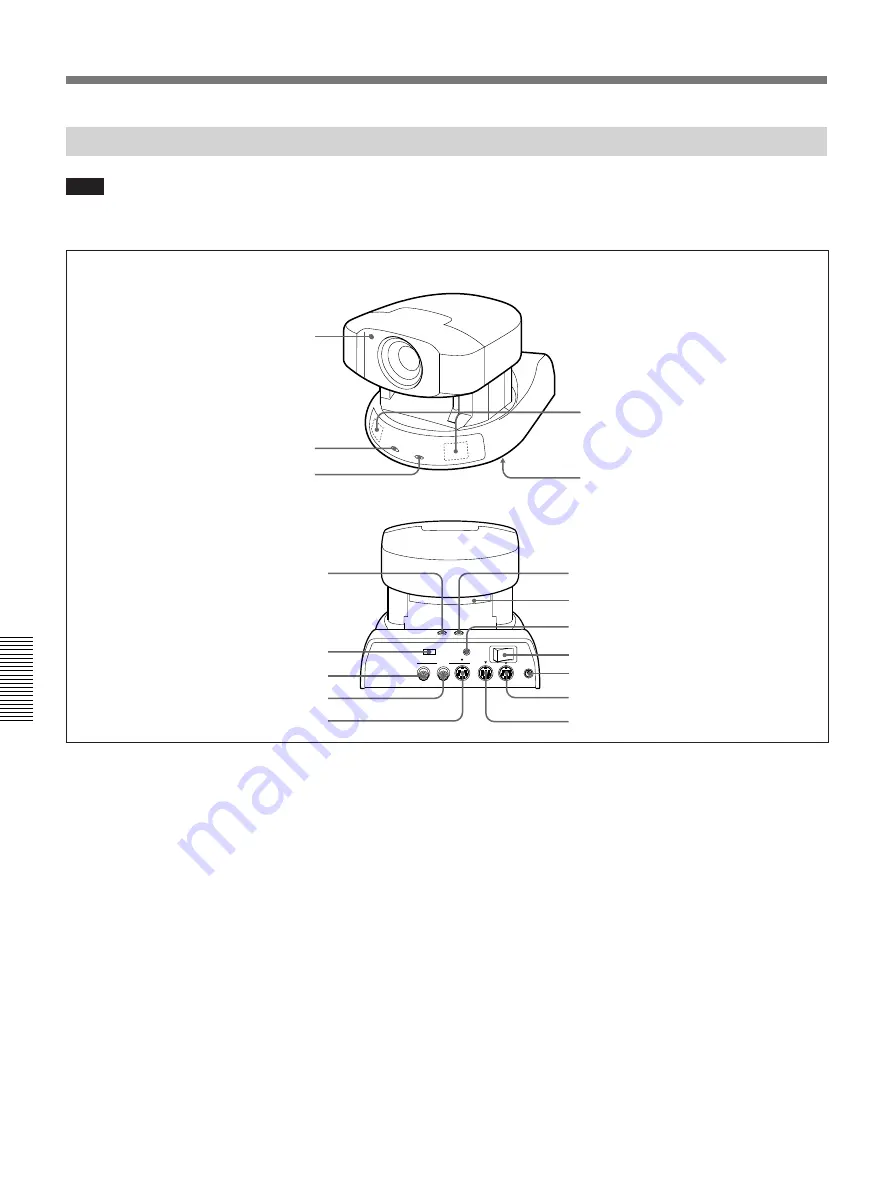
Camera Unit
Location and Function of Parts and Controls
Note
Do not connect any equipment to the AUDIO OUT,
VIDEO OUT, VISCA OUT, and MIC connectors.
1
Caution lamp
2
POWER lamp
3
4
Remote sensors
5
IR OUT switch
!¶
VISCA IN jack
!§
VISCA OUT jack
!∞
DC IN 13.5V jack
!¢
POWER switch
!£
MIC jack
!™
BACKUP switch
!¡
DATE button
6
TIME button
This button is used when setting the clock.
7
CAMERA NO. switch
This switch does not operate with this system.
8
AUDIO OUT jack
This jack cannot be used with this system.
9
VIDEO OUT jack
This jack cannot be used with this system.
0
S VIDEO OUT jack
Connect to the Rollabout Processor with the supplied
camera unit cable.
! ¡
DATE button
This button is used when setting the clock.
OUT
IN
OUT
1 2 3
CAMERA NO.
AUDIO
VIDEO
S VIDEO
VISCA
MIC
POWER
OFF
ON
DC IN
13.5V
6
TIME button
7
CAMERA NO. switch
0
S VIDEO OUT jack
9
VIDEO OUT jack
8
AUDIO OUT jack
1
Caution lamp
This lamp lights up when the camera is not capturing
the memorized subject correctly.
2
POWER lamp
This lamp lights up when the camera is turned on.
3
This lamp does not light up with this system.
4
Remote sensors
When operating the Rollabout Processor with the
Remote Commander, point it toward these sensors.
5
IR OUT switch
This switch must be turned on when the system is
activated.
Camera Unit
Содержание PCS-3000
Страница 8: ......
Страница 36: ......
Страница 122: ...Sony Corporation Printed in Japan ...
Страница 123: ...PCS 3000 3000P ...


