Sokkia SRX1 Скачать руководство пользователя страница 84

15. COORDINATE MEASUREMENT

76

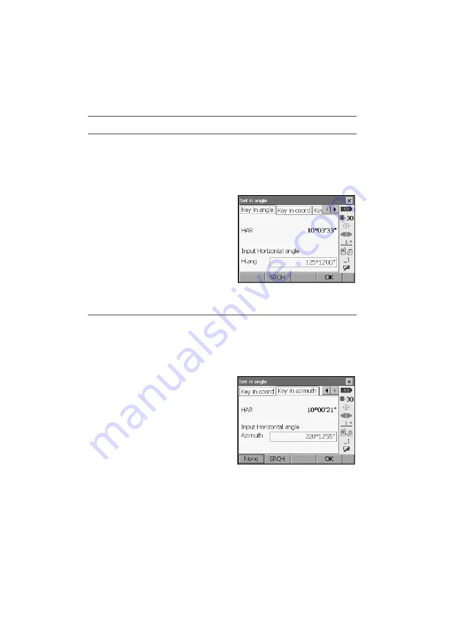
PROCEDURE Entering angle

1. Select "Backsight setup" in <Coordinate>.  <Set 

H angle> is displayed. 

.

<Set H angle> can also be displayed from the 
screen in step 4 of "15.1 Entering Instrument 
Station Data".

2. Select the Key in angle tab and enter the desired 

angle in "H.ang". 

[SRCH]

: Rotates the SRX in the direction of the 

desired angle.

3. Press 

[OK]

 to set the input values. <Coord. 

measurement> is displayed.  

PROCEDURE Entering azimuth

1. Select "Backsight setup" in <Coordinate>.  <Set 

H angle> is displayed. 

.

<Set H angle> can also be displayed from the 
screen in step 4 of "15.1 Entering Instrument 
Station Data".

2. Select the Key in azimuth tab and enter the 

desired angle in "H.ang". 

[SRCH]

: Rotates the SRX in the direction of the 

desired angle.

[None]

: Switches horizontal angle setting 

method.


"



Horizontal angle settings

"

3. Press 

[OK]

 to set the input values. <Coord. 

measurement> is displayed.  


Horizontal angle settings

Содержание SRX1

Страница 1: ...SURVEYING INSTRUMENTS Class 3R Laser Product Class 1 LED Product OPERATOR S MANUAL Series SRX SRX1 SRX2 SRX3 SRX5 Total Station H18 09 21 ...

Страница 2: ...Li ion S Li ion This is the mark of the Japan Surveying Instruments Manufacturers Association ...

Страница 3: ...function to output data saved in Program mode SDR to a connected host computer Command operations from a host computer can also be performed For details refer to Interfacing with the SOKKIA SDR Electronic Field Book and Command Explanations manuals and ask your Sokkia agent The specifications and general appearance of the instrument may be altered at any time and may differ from those appearing in...

Страница 4: ...bols The following conventions are used in this manual Softkey etc Indicates softkeys on the display and window dialog buttons Key etc Indicates keys on the operation panel Setting out etc Indicates screen titles Notes regarding manual style Except where stated SRX means SRX1 SRX2 SRX3 SRX5 in this manual Screens and illustrations appearing in this manual are of SRX3 Location of softkeys in screen...

Страница 5: ... operations in 4 PRODUCT OUTLINE and 5 BASIC OPERATION before you read each measurement procedure An overview of the available SRX functions is given in 4 1 Functions For selecting options and inputting figures see 5 1 Basic Key Operation For Auto Tracking measurement read this manual in conjunction with the On demand Remote Control System Manual Measurement procedures are based on continuous meas...

Страница 6: ...2 7 USING THE BATTERY 34 8 CONNECTING TO EXTERNAL DEVICES 36 8 1 Wireless Communication using Bluetooth Technology 36 8 2 Communication between the SRX and Companion Device 40 8 3 Connection via RS 232C cable 42 8 4 Connecting to USB devices 42 9 SETTING UP THE INSTRUMENT 44 9 1 Centering 44 9 2 Levelling 45 10 POWER ON OFF 48 10 1 Resolving Software Issues 49 10 2 Configuring the Touch Panel 49 1...

Страница 7: ...surement and Outputting the Data 70 15 COORDINATE MEASUREMENT 73 15 1 Entering Instrument Station Data 73 15 2 Azimuth Angle Setting 74 15 3 3 D Coordinate Measurement 77 16 RESECTION MEASUREMENT 79 16 1 Coordinate Resection Measurement 80 16 2 Height Resection Measurement 84 17 SETTING OUT MEASUREMENT 89 17 1 Using the Guide Light 89 17 2 Distance Setting out Measurement 90 17 3 Coordinates Setti...

Страница 8: ...R MESSAGES 137 23 CHECKS AND ADJUSTMENTS 140 23 1 Plate Level 140 23 2 Circular Level 141 23 3 Tilt Sensor 142 23 4 Collimation 145 23 5 Reticle 147 23 6 CCD reticle 149 23 7 Optical Plummet 151 23 8 Additive Distance Constant 152 24 Power Supply System 154 25 Target System 155 26 STANDARD EQUIPMENT 157 27 Optional Accessories 159 28 SPECIFICATIONS 161 29 REGULATIONS 168 30 EXPLANATION 173 30 1 Ma...

Страница 9: ...inted in or near the symbol This symbol indicates items which must always be performed Specific details are printed in or near the symbol Warning Do not use the unit in areas exposed to high amounts of dust or ash in areas where there is inadequate ventilation or near combustible materials An explosion could occur Do not perform disassembly or rebuilding Fire electric shock burns or hazardous radi...

Страница 10: ...d power supply voltage Fire or electrical shock could result Do not use damaged power cords plugs or loose outlets Fire or electric shock could result Do not use power cords other than those designated Fire could result Do not place articles such as clothing on the battery charger while charging batteries Sparks could be induced leading to fire Use only the specified battery charger to recharge ba...

Страница 11: ...hands and feet away from the tripod shoes when fixing the tripod in the ground A hand or foot stab wound could result Tighten the leg fixing screws securely before carrying the tripod Failure to tighten the screws could lead to the tripod legs extending causing injury Warning Do not use within the vicinity of hospitals Malfunction of medical equipment could result Use the instrument at a distance ...

Страница 12: ... is trapped inside the case it may cause the instrument to rust Charging the battery The battery BDC58 was not charged at the factory Charge the battery fully before using the SRX The Lithium Battery The lithium battery is used to maintain the SRX Calendar Clock function It can back up data for approximately 5 years of normal use but its lifetime may be shorter depending on circumstances Other pre...

Страница 13: ... wipe it with the wiping cloth If the display is dirty carefully wipe it with a soft dry cloth To clean other parts of the instrument or the carrying case lightly moisten a soft cloth in a mild detergent solution Wring out excess water until the cloth is slightly damp then carefully wipe the surface of the unit Do not use any organic solvents or alkaline cleaning solutions Store the instrument in ...

Страница 14: ...umulative output during distance measurement and tracking in Auto Tracking mode is equivalent to class 1 Warning Use of controls or adjustments or performance of procedures other than those specified herein may result in hazardous radiation exposure Follow the safety instructions on the labels attached to the instrument as well as in this manual to ensure safe use of this laser and LED product Cau...

Страница 15: ...res stipulate procedures beforehand for transporting the injured and contacting physicians in case there are laser induced injuries Persons working within the range of the laser beam are advised to wear eye protection which corresponds to the laser wavelength of the instrument being used Areas in which the lasers are used should be posted with laser warning notices If Search or Track is selected i...

Страница 16: ...nd Remote Control system data collectors and computers for even greater efficiency gains in the field Bluetooth device address and passkey settings afford greater security when transmitting data wirelessly 8 CONNECTING TO EXTERNAL DEVICES 3 High accuracy with reflectorless measurement Sokkia s own optics electrical circuits and processing algorithms combine to provide superior reflectorless accura...

Страница 17: ...low of measurement operation Pressing the trigger key located on the side of the SRX will perform exactly the same operation as the bolded softkey in the current screen This allows the user to continue operation without having to return to the display to press softkeys making operations such as resection measurement even simpler 4 2 Parts of the Instrument Trigger key 9 Wide range of advanced prog...

Страница 18: ...ction 16 Guide light 17 Bluetooth antenna 18 Instrument height mark 19 Vertical jogging knob 20 Trigger key 21 Horizontal jogging knob 22 Stylus pen holder 23 Combined communications and power supply connector 24 CF card slot 6 USING THE CF CARD SLOT 25 USB ports 8 CONNECTING TO EXTERNAL DEVICES 26 Plate level adjusting screw 27 Plate level 28 Telescope eyepiece screw 29 Telescope focussing ring 3...

Страница 19: ...ned from the telescope eyepiece side Peep sight Use peep sight to aim the SRX in the direction of the measurement point Turn the instrument until the triangle in the peep sight is aligned with the target Instrument height mark The height of the SRX is 236mm from tribrach dish to this mark Instrument height is input when setting instrument station data and is the height from the measuring point whe...

Страница 20: ... levers towards you and slide the handle back and up to remove The handle lock levers once released will return to the original position Make sure that the handle does not fall while being removed Removing the handle requires a certain amount of force As a result always hold firmly when removing Handle Green indicates lock locked state Lock lever ...

Страница 21: ...n until a click is heard Check that the handle lock levers once released return to the closed position 3 Slide the handle locks away from you to lock the handle Check that the green sections of the handle locks are showing Securely lock the handle in place before starting measurement Mounting brackets Handle mounting position Handle locked ...

Страница 22: ...on The antenna may be damaged if forcibly bent in an incorrect direction The antenna cannot be bent to angles exceeding 90 Beam detector for On demand Remote Control System Always open the beam detector cover when using the On demand Remote Control system The beam detector cover can be damaged if forced open beyond a certain angle Always close the beam detector cover before moving the instrument N...

Страница 23: ...Switching between modes is not possible during distance measurement or while the motor is in operation 4 3 Mode Configuration Basic mode Status screen Version OK ESC Meas mode Navigable with tabs Program mode Settings mode SETTINGS SETTINGS mode PROGRAM Program mode SDR 5 4 SETTINGS Mode SETTINGS 5 2 Display Functions Chapters 15 20 Chapter 21 Series SRX SDR Software Reference Manual ...

Страница 24: ...ly and take measures to prevent further interference e g connect using an interface cable In the case that the instrument causes radio interference with portable specified low power radio equipment contact your Sokkia agent Although a radio station license is not required for this instrument bear in mind the following points when using Bluetooth technology for communication Do not use within the v...

Страница 25: ...pointing the antenna vertically towards the ground Perform communication at a distance of 2m or more from electrical devices such as audio visual equipment and office automation equipment In the case of microwave ovens which are especially susceptible to interference this distance should be increased to 3m Moreover operation near televisions and radios may lead to problems with reception Ensure th...

Страница 26: ...lumination key backlight ON OFF Switches the screen backlight brightness setting SETTINGS Switches to screens for tilt correction returned signal checking motor operation fixed velocity rotation and general configuration SETTINGS ESC Returns to the previous screen mode PROGRAM Switches between Basic mode and Program mode SDR TARGET Switches between target types PROGRAM SETTINGS TARGET OFF ESC TAB ...

Страница 27: ...lphabetic lower case alphabetic and numeric characters A selection can also be made by tapping the status bar icon with the stylus pen Press and hold until a beep sounds Turns the laser pointer guide light ON OFF F1 to F4 Select the function matching the softkeys FUNC CTRL Toggles between softkey pages 0 to 9 Input numeral or symbol printed above the key during numeric input mode Input alphabetic ...

Страница 28: ... the status bar second from bottom until _a is displayed 2 Press 7 three times c is displayed Move the cursor selection item up down Move the cursor selection item left right or selects other option TAB Shift to the next item SPACE Display other options Select accept the option Move tab cursor in tab up down Display next tab at left right ESC Return to previous screen Moves tab left right ...

Страница 29: ... displayed 4 Press Press 5 twice m is displayed 5 Continue to input letters Press to complete inputting Example selecting a reflector type Method 1 1 Select EDM in the second page of Measure mode or EDM in SETTINGS mode 2 Move to Reflector using TAB ...

Страница 30: ...ptions 4 Select an option using 5 Press to confirm selection Method 2 1 Select EDM in the second page of Measure mode or EDM in SETTINGS mode 2 Move to Reflector using TAB 3 Switch between Prism 360 Prism Sheet and Reflectorless using 4 Press to confirm selection ...

Страница 31: ...reen tap the cross in the top right corner or press ESC Tabs softkey allocations displayed tab items and character sizes can all be changed in accordance with user preferences 21 CHANGING THE SETTINGS Status screen 5 2 Display Functions Operation Method Tap Lightly tap the display once This operation is equivalent to that of clicking a mouse button when using a computer Double tap Lightly tap the ...

Страница 32: ...ess ZA when allocated to the Meas mode screen The capitalized letter in the softkey indicates the currently selected mode 21 1 Observation Conditions 3 Horizontal angle Press R l when allocated to the Meas mode screen to switch the display status The capitalized letter in the softkey indicates the currently selected mode HAR Horizontal angle right HAL Horizontal angle left 21 6 Allocating Key Func...

Страница 33: ...ify the orientation of the graphic tab display and which point target or station to set at the center of the display DEF Returns to the original orientation display ZoomIn Zooms in ZoomOut Zooms out Selecting menus To select a menu tap the touch panel or press the relevant number key Instrument station Scale units m Arrow indicates north Target point Number ...

Страница 34: ...8 external battery BDC61 Temperature 25 EDM on The remaining batter power displayed when distance measurement is in progress may differ to that displayed at other times Level 3 Full power Level 2 Plenty of power remains Level 1 Half or less power remains Level 0 Little power remains Flashes red and black No power Red display in the center of the screen Stop measurement and charge the battery 7 USI...

Страница 35: ...o Tracking set Motor settings 11 1 Auto Pointing Settings 12 1 Auto Tracking Settings Auto Tracking and Auto Pointing cannot be performed when Reflectorless has been selected as the target type Auto Tracking cannot be performed when Sheet has been selected as the target type will be displayed An arrow indicating turn direction will be displayed when the SRX is rotating at a fixed velocity Fixed ve...

Страница 36: ...r device blue antenna Connection via Bluetooth SRX set as Slave device green antenna When Bluetooth is selected SRX set as Master device a connection can be initiated canceled by tapping An arrow symbol is displayed while data is being transmitted This icon is not displayed in Program mode SDR Connection status is displayed as follows i Connection via Bluetooth When SRX is set as the Master device...

Страница 37: ...racters Tab Moves the cursor to the next text box CAP Alternates between upper and lower case alphabetic characters and numbers symbols Shift Alternates between upper and lower case alphabetic characters and numbers symbols Is canceled after inputting a single character Ctl No function Del A Delete the character to the left right or deletes the entire text in the active section Move the cursor lef...

Страница 38: ...or settings The instrument can be automatically rotated to a desired vertical and or horizontal angle by specifying the angle in the Motor tab and selecting ROTATE The following operations can be performed using the softkeys in the second page READ Read in coordinates from Program mode SDR and set as the desired angle COORD Specify rotation angle by inputting coordinates in Key in coord TURN Rotat...

Страница 39: ...he SRX horizontal angle and telescope can be rotated using the controls in the Fixed velocity rotation tab Speed settings are from 1 to 16 Tap the touch panel in the desired rotation direction Press ESC or tap the red center circle to stop rotation ...

Страница 40: ... and or editing using the SRX s USB ports 8 CONNECTING TO EXTERNAL DEVICES Do not remove the CF card during data read write Make sure the eject button is fully depressed when a CF card is inserted A protruding eject button will be depressed when the card cover is closed causing the card to be ejected Always close the card cover before moving the instrument The card cover can be damaged if forced o...

Страница 41: ...ng the CF card 1 Push the catch on the card cover to open 2 Press the eject button once to release Once the eject button is fully protruded press once more to remove the card from the card slot 3 Close the card cover Catch Card cover Eject button ...

Страница 42: ...er is switched on a warm boot occurs File and folder data may be lost as a result When installing removing the battery make sure that moisture or dust particles do not come in contact with the inside of the instrument PROCEDURE Mounting the battery 1 Slide down the catches on the battery cover to open 2 Insert the battery in the direction of the arrow printed on the side 3 Close the battery cover ...

Страница 43: ...ery cover to open 2 Retract the battery 3 Close the battery cover A click is heard when the cover is secure Battery cover If the battery cover is open during power ON SRX notifies you by displaying the screen below and beeping When the battery cover is closed the previous screen is restored ...

Страница 44: ...RX Security functions such as Bluetooth device address and passkey can be used to provide a level of protection for wireless communication Bluetooth device address This is a number unique to one particular Bluetooth device used to identify devices during communication This number consists of 12 characters numbers 0 to 9 and letters from A to F Some devices may be referred to by their Bluetooth dev...

Страница 45: ...e Master device To initiate connections from the paired device side set the SRX as Slave The factory setting is Slave Register companion devices Master cannot be selected when no companion devices have been registered 3 Select in Link a companion device from among the Bluetooth devices already registered in the SRX Registering devices PROCEDURE Registering Bluetooth companion devices Companion dev...

Страница 46: ...intended companion device Even if Authentication is set to No a passkey is requested when authentication is set on the companion device being used Up to 16 numeral characters can be input Input characters will be displayed as asterisks e g The passkey was set to 0123 at the factory 6 Press OK to finish settings ...

Страница 47: ...n the Bluetooth tab and press LIST to display a list of all registered devices Data collector devices can be set in the Serial tab and devices for use with the SFX Dial Up Program in the SFX Dial Up tab 4 Register your Bluetooth device s Press Add to display Add device Input the device name and Bluetooth address and press OK Up to 12 hexadecimal digits can be input ...

Страница 48: ...n the Bluetooth tab to display the device name and Bluetooth address for the SRX Bluetooth module Register the Bluetooth address displayed here in the paired device Bluetooth communication causes SRX battery power to be depleted at a higher than average rate Under the Slave setting the SRX is constantly being searched for by communicable devices and therefore consumes an ever greater amount of pow...

Страница 49: ...of Meas mode When Connect is pressed the SRX searches for the device selected in Link and a connection starts When a connection has been successfully established is displayed in the status bar When SRX is set as the Slave device the establishing of a connection can only be initiated canceled by the companion device set as Master The establishing of a connection can also be initiated by tapping in ...

Страница 50: ...to different types of devices PROCEDURE Basic cable settings 1 Connect the cable Cables 27 OPTIONAL ACCESSORIES 2 Select Comms in SETTINGS mode Set communication conditions in the Comms setup tab Set Comms mode to RS232C 8 3 Connecting to USB devices Port name Device type USB port 1 USB memory devices etc USB port 2 computers etc 8 4 Connection via RS 232C cable USB port 1 USB port 2 ...

Страница 51: ...ERNAL DEVICES 3 Set options in the RS232C tab according to the selection made in the Comms setup tab factory settings Baud rate 1200 2400 4800 9600 19200 38400bps Data bits 8 7 bits Parity Not set Odd Even Stop bit 1 2 bits ...

Страница 52: ...head is positioned over the surveying point Make sure the tripod shoes are firmly fixed in the ground 2 Place the instrument on the tripod head Supporting it with one hand tighten the centering screw on the bottom of the unit to make sure it is secured to the tripod 3 Looking through the optical plummet eyepiece turn the optical plummet eyepiece to focus on the reticle Turn the optical plummet foc...

Страница 53: ...arthest from the offcenter direction of the bubble Adjust one more tripod leg to center the bubble 3 Turn the upper part of the instrument until the plate level is parallel to a line between levelling foot screws A and B Center the air bubble using levelling foot screws A and B The bubble moves towards a clockwise rotated levelling foot screw 4 Turn the upper part of the instrument though 90 The p...

Страница 54: ...nt in this direction Or adjust the plate level 23 1 Plate Level 6 Turn the instrument and check to see if the air bubble is in the same position in all directions If it is not repeat the levelling procedure 7 Loosen the centering screw slightly Looking through the optical plummet eyepiece slide the instrument over the tripod head until the surveying point is exactly centered in the reticle Retight...

Страница 55: ...ircle is 3 and the range of the outside circle is 4 5 4 Center z in the circular level 9 2 Levelling steps 1 to 2 5 Turn the instrument until the telescope is parallel to a line between levelling foot screws A and B 6 Set the tilt angle to 0 using foot screws A and B for the X direction and levelling screw C for the Y direction 7 Press ESC to return to Meas mode ...

Страница 56: ... the instrument was powered OFF when the instrument is powered back ON All parameter settings are also saved Even if remaining battery power is completely depleted this function will remain active for 1 minute after which it is canceled Replace a depleted battery as soon as possible PROCEDURE Power OFF Press while pressing When there is almost no battery power remaining the battery mark in the sta...

Страница 57: ...ogram you should try a warm boot A warm boot will not erase surveying data in Program mode SDR but will cancel the resume function Whenever possible transmit the data to a personal computer before rebooting If the problem is not resolved with a warm boot the next step is to perform a cold boot PROCEDURE 1 Power OFF the instrument 2 Press while pressing The instrument is reset and powers ON as norm...

Страница 58: ...SRX is powered OFF from a paired Bluetooth device during Bluetooth communication the screen shown at right will be displayed Powering ON the SRX from the paired device or by pressing on the SRX itself redisplays the screen appearing before the instrument was powered OFF Powering OFF the SRX during Bluetooth communication will cancel the Bluetooth connection If this screen is displayed continuously...

Страница 59: ...is located at the zenith In this case manually sight the target 11 3 Manually Sighting the Target If more than one prism is located in the field of sight during Auto Pointing an operation error will occur and the SRX will not be able to find the target A prism beyond glass cannot be searched because a measurement error occurs If an obstacle blocks the laser beam path between the SRX and the prism ...

Страница 60: ...he criteria for completing sighting are more stringent Rapid mode should be used when supporting the pole by hand if Time out is displayed before the SRX completes sighting as a result of vibration or completing Auto Pointing takes too long Srch method Selects search before distance measurement option When set to G S the SRX will search for the target in the area specified in the Search area tab W...

Страница 61: ...in the Search area tab Drag the box to specify the desired or area or input vertical and horizontal angle values Angle values can only be specified in 1 30 steps e g 15 00 16 30 18 00 etc Input values not conforming to this format will be automatically rounded up 3 Press OK ...

Страница 62: ... Settings 11 2 Auto Pointing Function for Target Sighting Softkey Function DIST Performs Auto Pointing then distance and angle measurement SRCH Performs Auto Pointing then distance and angle measurement H ANG Performs Auto Pointing then sets current angle to the specified angle 0 SET Performs Auto Pointing then sets current angle to 0 RC Rotates in the direction specified by the On demand Remote C...

Страница 63: ...he vertical and horizontal jogging knobs for fine sighting adjustments 3 Turn the telescope focussing ring to focus on the target Turn the vertical and horizontal fine motion screws to align the target with the reticle The last adjustment of each fine motion screw should be in the clockwise direction 4 Readjust the focus until there is no parallax Readjust the focus with the focussing ring until t...

Страница 64: ...re than one prism is located in the field of sight during Auto Tracking an operation error will occur and the SRX will not be able to find the target The prism beyond the glass can not be searched because measurement error occurs If an obstacle blocks the laser beam path between the SRX and the prism SRX cannot find the target correctly Position the prism in alignment with the objective lens In sh...

Страница 65: ... to aim the objective lens in the general direction of the target The vertical and horizontal jogging knobs can be used for precise adjustments of the instrument and telescope 2 Select DIST RC Cont or SRCH in any Meas mode screen The telescope and top half of the instrument rotate and target auto search begins When the target is found the instrument sights the center of the prism and Auto Tracking...

Страница 66: ...rminates Start Auto Tracking procedure again from step 1 The following softkeys can also be used for Auto Pointing when A T Setting in Motor configuration is set to Track Softkey Function DIST Performs Auto Pointing then Auto Tracking distance measurement SRCH Performs Auto Pointing then Auto Tracking distance measurement H ANG Sets current angle to a specified angle then performs Auto Pointing Au...

Страница 67: ...ng operation then performs Auto Pointing Auto Tracking AT On Performs Auto Pointing then Auto Tracking ROTATE Automatically rotates the instrument to the specified vertical and horizontal angles then performs Auto Pointing Auto Tracking TURN Rotates the SRX 180 then performs Auto Pointing Auto Tracking ...

Страница 68: ...locating Key Functions Use the 0SET function to measure the included angle between two points The horizontal angle can be set to 0 at any direction PROCEDURE 1 Sight the first target as at right 10 3 TARGET SIGHTING 2 In the first page of the Meas mode screen press 0SET 0SET will flash so press 0SET again The horizontal angle at the first target becomes 0 3 Sight the second target 13 1 Measuring t...

Страница 69: ...61 13 ANGLE MEASUREMENT The displayed horizontal angle HAR is the included angle between two points ...

Страница 70: ...e that is input as the horizontal angle is displayed Press SRCH to rotate the SRX in the direction of the desired angle The same setting can also be performed with coordinate and azimuth input 15 2 Azimuth Angle Setting 4 Press OK to confirm the input value and display the new horizontal angle 5 Sight the second target The horizontal angle from the second target to the value set as the horizontal ...

Страница 71: ...MENT Pressing HOLD performs the same function as above Press HOLD to set the displayed horizontal angle Then set the angle that is in hold status to the direction you require Allocating HOLD 21 6 Allocating Key Functions ...

Страница 72: ...n or Coll crn is set to Yes in Obs condition PROCEDURE 1 Sight the point you will use as the reference angle and set it as the reference angle Sight the reference point and press 0SET or input the reference point angle 13 1 Measuring the Horizontal Angle between Two Points Horizontal Angle 0 13 2 Setting the Horizontal Angle to a Required Value Horizontal Angle Hold 2 Press SETTINGS to switch to S...

Страница 73: ...rtical angle from the coordinates 4 After confirming the coordinates press ROTATE The SRX moves to the point target entered in step 3 The following explains angle measurement and the features used to output measurement results to a computer or other external devices 6 1 CONNECTING TO EXTERNAL DEVICES Cables 27 OPTIONAL ACCESSORIES Output format and command operations Interfacing with the SOKKIA SD...

Страница 74: ... settings accurate measurement results cannot be obtained Accurate measurement results cannot be obtained if the objective lens is dirty Dust it off with the lens brush first to remove minute particles Then after providing a little condensation by breathing on the lens wipe it off with the wiping cloth During reflectorless measurement if an object with a high reflective factor metal or white surfa...

Страница 75: ...or the measurement is returned When is not displayed accurately resight the target BEEP OFF Sets a buzzer sound when measurement is possible Press to switch on and off DIST Returns to Meas mode and starts distance measurement This softkey is not displayed when the returned signal checking function is accessed from Program mode SDR 3 Press OFF to finish signal checking Press ESC or tap the cross in...

Страница 76: ... time as distance The search range can be set 12 1 Auto Tracking Settings Caution The laser beam is emitted during Auto Pointing and Auto Tracking PROCEDURE 1 Face the SRX in the direction of the target Use the peep sight to aim the SRX and telescope toward the target 11 TARGET SIGHTING 14 2 Using the Guide Light Light status Meaning Slow flashing Red and green simultaneously Waiting Fast flashing...

Страница 77: ...s selected measurement automatically stops after a single measurement During fine average measurement the distance data is displayed as S1 S2 to S9 When the designated number of measurements has been completed the average value of the distance is displayed in the SA line The distance and angle that are most recently measured remain stored in the memory until the power is off and can be displayed a...

Страница 78: ...asurement results are output to the external device Output type 21 6 Allocating Key Functions 21 1 Observation Conditions 4 Press STOP to finish data output and return to the Meas mode An REM measurement is a function used to measure the height to a point where a target cannot be directly installed such as power lines overhead cables and bridges etc The height of the target is calculated using the...

Страница 79: ...URE 1 Set the target directly under or directly over the object and measure the target height with a tape measure etc Press HT and enter the target height 2 Select REM in Menu 3 Sight the target and press DIST to start measurement Press STOP to stop the measurement ...

Страница 80: ...ement is started The height from the ground to the object is displayed in Ht Press STOP to stop the measurement To re observe the target sight the target then press DIST To continue REM measurement press REM When measurement data already exists select REM in Menu as in step 2 to proceed to step 4 and start REM measurement Press STOP to stop the measurement ...

Страница 81: ...ntered in advance It is possible to allocate softkeys in measurement menus to suit various applications and the ways that different operators handle the instrument 21 6 Allocating Key Functions Before performing coordinate measurement enter instrument station coordinates instrument height and target height PROCEDURE 1 First measure the target height and instrument height with a tape measure etc 2 ...

Страница 82: ...d in coordinate data registered in Program mode SDR Series SRX SDR Software Reference Manual 4 Press OK to set the input values Set H angle is displayed again Based on the instrument station coordinates and backsight station coordinates which have already been set the azimuth angle of the backsight station is calculated 15 2 Azimuth Angle Setting ...

Страница 83: ... coordinate data registered in Program mode SDR Series SRX SDR Software Reference Manual SRCH Rotates the SRX in the direction of the desired angle Sight the backsight station and press DIST Press STOP to display the distance calculated from coordinates the measured distance and the difference between the two Press YES to set the azimuth angle and display Coord measurement None Switches horizontal...

Страница 84: ... Press OK to set the input values Coord measurement is displayed PROCEDURE Entering azimuth 1 Select Backsight setup in Coordinate Set H angle is displayed Set H angle can also be displayed from the screen in step 4 of 15 1 Entering Instrument Station Data 2 Select the Key in azimuth tab and enter the desired angle in H ang SRCH Rotates the SRX in the direction of the desired angle None Switches h...

Страница 85: ...rument station and backsight station The coordinate values of the target are calculated using the following formulae N1 Coordinate N0 S x sinZ x cosAz E1 Coordinate E0 S x sinZ x sinAz Z1 Coordinate Z0 S x cosZ ih fh N0 Station point N coordinate S Slope distance ih Instrument height E0 Station point E coordinate Z Zenith angle fh Target height Z0 Station point Z coordinate Az Direction angle Null...

Страница 86: ...ect the Graphic tab to display coordinates on a graph By pressing HT the instrument station data can be reset When the target height of the next target is different reenter the target height before beginning the observation 3 Sight the next target and press DIST to begin measurement Continue until all targets have been measured 4 When coordinate measurement is completed press ESC or tap the cross ...

Страница 87: ...asurement and between 3 and 10 known points by angle measurement The more known points there are and the more points there are whose distance can be measured the higher the precision of the coordinate value calculation It is possible to allocate softkeys in the Coord measurement menu to suit various applications and the ways that different operators handle the instrument 21 6 Allocating Key Functi...

Страница 88: ...nown point 3 Input the known point After setting the coordinates and target height for for the first known point press OUT to move to the second point Press READ to read in coordinate data registered in Program mode SDR Press IN to return to settings for the previous point When all required known points have been set press OK 16 1 Coordinate Resection Measurement ...

Страница 89: ...target height here Press NO to return to the screen in step 3 and perform measurement again 6 Repeat procedures 3 to 4 in the same way from subsequent points When the minimum quantity of observation data required for the calculation is present CALC is displayed 7 Press CALC or YES to automatically start calculations after observations of all known points are completed Instrument station coordinate...

Страница 90: ...form calculation again without the point designated in step 8 The result is displayed If there are no problems with the result go to step 10 If problems with the result occur again perform the resection measurement from step 3 Press RE OBS to measure the point designated in step 8 If no points are designated in step 8 all the points or only the final point can be observed again Press ADD when ther...

Страница 91: ...s NO to return to Resection Menu without setting the azimuth angle Horizontal angle settings H set horizontal angle to measured value H Az set horizontal angle to the same value as azimuth angle Az set azimuth angle only It is also possible to perform resection measurement by pressing RESEC when allocated to the Meas mode screen Allocating RESEC 21 6 Allocating Key Functions ...

Страница 92: ...1 Select Resection in Menu 2 Select Elevation to display Resection Known point 3 Input the known point After setting the elevation and target height for for the first known point press OUT to move to the second point Press READ to read in data registered in Program mode SDR Press IN to return to settings for the previous point When all required known points have been set press OK 16 2 Height Resec...

Страница 93: ...dures 3 to 4 in the same way from the second point When the minimum quantity of observation data required for the calculation is present CALC is displayed 6 Press CALC or YES to automatically start calculations after observations of all known points are completed Instrument station elevation and standard deviation which describes the measurement accuracy are displayed in the Result tab Standard de...

Страница 94: ...problems with the result go to step 10 If problems with the result occur again perform the resection measurement from step 3 Press RE OBS to measure the point designated in step 8 If no points are designated in step 8 all the points or only the final point can be observed again Press ADD when there is a known point that has not been measured or when a new known point is added 9 Press OK to finish ...

Страница 95: ...ess The NE coordinates are found using angle and distance observation equations and the instrument station coordinates are found using the method of least squares The Z coordinate is found by treating the average value as the instrument station coordinates ...

Страница 96: ...one of the following measures 1 Move the instrument station as close as possible to the center of the triangle 2 Observe one more known point which is not on the circle 3 Perform a distance measurement on at least one of the three points In some cases it is impossible to calculate the coordinates of the instrument station if the included angle between the known points is too small It is difficult ...

Страница 97: ...ting out coordinates N coordinates of setting out data E or Z coordinates can be input in the above formula Height difference REM setting out measurement Displayed value height measured REM data REM data of setting out data Setting out data can be input in various modes slope distance horizontal distance height difference coordinates and REM measurement It is possible to allocate softkeys in the S...

Страница 98: ...ring repeated measurement Green and red alternate flashing Search error error screen only Distance measurement error no signal sighting error Light status Meaning Increased flashing speed From position of poleman Move target away from SRX Decreased flashing speed From position of poleman Move target toward SRX Fast flashing Target is at correct distance Red From position of poleman Move target lef...

Страница 99: ...ng Enter data for the instrument station and press OK to move to Backsight setup 15 1 Entering Instrument Station Data Press READ to read in coordinate data registered in Program mode SDR Series SRX SDR Software Reference Manual 3 Set the azimuth angle for the backsight station Press OK to return to Setting out 15 2 Azimuth Angle Setting ...

Страница 100: ...from S slope distance H horizontal distance V height difference and Ht REM When READ is pressed coordinates registered in Program mode SDR can be recalled and used The distance selected according to the selected distance input mode is calculated using these coordinate values Series SRX SDR Software Reference Manual Press COORD in the second page and input coordinates in Key in coord The angle and ...

Страница 101: ... when viewing the display in Face 2 Y Viewed from SRX Move target to the left Z Viewed from SRX Move target to the right YZ Target position is correct Viewed from SRX Move target closer Viewed from SRX Move target away Viewed from SRX Target position is correct Move target upward Move target downward Target position is correct Each time Shvr is pressed the distance input mode changes from H horizo...

Страница 102: ...ntil the distance to the setting out point reads 0m When the target is moved within the allowed range all distance and position arrows are displayed 8 Press OK to return to Setting out Set the next setting out point to continue setting out measurement ...

Страница 103: ...red coordinate location can be set out Previously recorded setting out points can be placed in order Up to 30 points can be recorded To find the Z coordinate attach the target to a pole etc with the same target height PROCEDURE 1 Select Setting out in Menu to display Setting out 2 Select Station setup to display Height setting If necessary enter data for Backsight setup 17 2 Distance Setting out M...

Страница 104: ...recorded angle data or press ADD to record new data Press DEL in the second page to delete the selected setting out point Press DELALL in the second page to delete all setting out points 4 Select a setting out point in the first screen of step 3 and press OK to display Set out Coords Press H ROTA to automatically rotate the SRX until the angle of the setting out point reads 0 ...

Страница 105: ... out point is located is displayed on the SRX The sighting point measurement results currently installed position of the target are displayed Set out Coords can also be displayed by selecting Set out coords in Setting out Switch between the tabs to display different sets of information Move the target closer further away and upward downward to find the correct distance 0 is displayed to the settin...

Страница 106: ...Select Station setup in Setting out to display Height setting If necessary enter data for Backsight setup 17 2 Distance Setting out Measurement steps 2 to 3 3 Select SO data setting In Setting out to display SO data setting Press Shvr until the distance input mode is Ht Input height from the surveying point to the position to be set out in SO Height If necessary input the angle to the point to be ...

Страница 107: ...age to start REM measurement The distance height difference and direction to move the target until the sighting point and setting out point are located is displayed on the SRX The sighting point measurement results are displayed Press STOP to stop measuring Find the setting out point by moving the telescope until the distance to the setting out point reads 0m Movement indicator Red indicates that ...

Страница 108: ...REMENT 100 Press CNFG to set setting out accuracy When the position of the target is within this range both arrows will be displayed to indicate that the target position is correct 8 Press ESC to return to SO data setting ...

Страница 109: ...tion setup 15 1 Entering Instrument Station Data Backsight setup 15 2 Azimuth Angle Setting It is possible to allocate softkeys in the Offset menu to suit various applications and the ways that different operators handle the instrument 21 6 Allocating Key Functions Finding it by entering the horizontal distance from the target point to the offset point When the offset point is positioned to the le...

Страница 110: ...ight the offset point and press DIST in the screen of step 3 to start measurement Press STOP to stop the measurement The measurement results are displayed Press HVD nez to switch results for the target point between distance angle values and coordinate elevation values 5 Press OK in the screen in step 4 to return to Offset On the left of the target point On the right of the target point Closer tha...

Страница 111: ...nd measure the distance to the offset points and the horizontal angle of the target point PROCEDURE 1 Set the offset points close to the target point making sure the distance from the instrument station to the target point and the height of the offset points and the target point are the same then use the offset points as the target 2 Select Offset in Menu to display Offset Select Angle offset 18 2...

Страница 112: ...ss STOP to stop the measurement 4 Sight the target point and press H ANG Press HVD nez to switch results for the target point between distance angle values and coordinate elevation values 5 Press OK in the screen in step 4 to return to Offset Results for target point Results for offset point ...

Страница 113: ...asurement easily using the optional equipment the 2 point target 2RT500 K When using this 2 point target be sure to set prism constant to 0 25 TARGET SYSTEM How to use 2 point target 2RT500 K Install the 2 point target with its tip at the target point Face the targets toward the instrument Measure the distance from the target point to the 2nd target Set the prism constant to 0mm PROCEDURE 1 Instal...

Страница 114: ...ctor type and press OK to finish settings Press LIST to edit the prism constant and aperture in Reflector setting 4 Sight the 1st target and press DIST to start measurement Press STOP to stop the measurement The measurement results are displayed Press YES to confirm 5 Sight the 2nd target and press DIST to start measurement Press STOP to stop the measurement The measurement results are displayed ...

Страница 115: ...NT 6 Press YES to display results for the target point Press HVD nez to switch results for the target point between distance angle values and coordinate elevation values 7 Press YES in the screen in step 4 to return to Offset ...

Страница 116: ...he instrument It is possible to change the last measured point to the next starting position Measurement results can be displayed as the gradient between two points It is possible to allocate softkeys in the MLM menu to suit various applications and the ways that different operators handle the instrument 21 6 Allocating Key Functions PROCEDURE 1 Select MLM in Menu 19 1 Measuring the Distance betwe...

Страница 117: ...rts 3 Sight the next target and press MLM to begin observation Slope distance horizontal distance and height difference between multiple points and the starting position can be measured this way Press DIST to re observe the starting position Sight the starting position and press DIST When MOVE is pressed the last target measured becomes the new starting position to perform missing line measurement...

Страница 118: ...the last measured point to the next starting position PROCEDURE 1 Observe the starting position and target following steps 1 to 3 in 19 1 Measuring the Distance between 2 or more Points 2 After measuring the targets press MOVE 19 2 Changing the Starting Point ...

Страница 119: ... intheconfirmationmessagewindow Press NO to cancel measurement 3 The last target measured is changed to the new starting position 4 Perform missing line measurement following steps 2 to 3 in 19 1 Measuring the Distance between 2 or more Points ...

Страница 120: ...ument 21 CHANGING THE SETTINGS An error will occur if only two points or less are entered or recalled when specifying an enclosed area Be sure to observe or recall points on an enclosed area in a clockwise or counterclockwise direction For example the area specified by entering or recalling point numbers 1 2 3 4 5 or 5 4 3 2 1 implies the same shape However if points are not entered in numerical o...

Страница 121: ...ered coordinates can be recalled and used in subsequent measurements PROCEDURE Surface area calculation using registered coordinate data 2 Press MEAS to display Area calculation measurement Sight the first point on the line enclosing the area and press DIST Measurement begins and the measured values are displayed Press STOP to stop measuring ...

Страница 122: ... steps 3 to 4 until all points have been measured Points on an enclosed area are observed in a clockwise or counterclockwise direction For example the area specified by entering point numbers 1 2 3 4 5 or 5 4 3 2 1 implies the same shape After all known points necessary to calculate the surface area have been observed CALC is displayed ...

Страница 123: ...ss in the top right corner to quit area calculation PROCEDURE Surface area calculation using registered coordinate data Coordinate data registered in Program mode SDR can be recalled and used for area calculations Series SRX SDR Software Reference Manual 1 Select Area calc in Menu 2 Press READ to display the list of registered coordinate data ...

Страница 124: ...ps 2 to 3 until all points have been read in Points on an enclosed area are read in a clockwise or counterclockwise direction After all known points necessary to calculate the surface area have been observed CALC is displayed 5 Press CALC to display the calculated area 6 Press OK to return to Area key in coord Press ESC or tap the cross in the top right corner to quit area calculation ...

Страница 125: ...ment requirements SETTINGS mode can be accessed either by pressing SETTINGS or the SETTINGS icon in Top The following chapters provide details of items in SETTINGS mode Communication settings 8 CONNECTING TO EXTERNAL DEVICES Motor settings 11 1 Auto Pointing Settings 12 1 Auto Tracking Settings Instrument configurations 23 3 Tilt Sensor 23 5 Reticle 21 1 Observation Conditions ...

Страница 126: ...rement Automatic tilt angle compensation mechanism The vertical and horizontal angles are automatically compensated for small tilt errors using the 2 axis tilt sensor Read the automatically compensated angles when the display has stabilized The horizontal angle error vertical axis error fluctuates according to the vertical axis so when the instrument is not completely leveled changing the vertical...

Страница 127: ...PWR On Yes No Yes Serial Yes Bluetooth Color 1 2 monochrome Backlight settings Pressing switches the brightness level of the backlight between the settings made in Backlight Reticle ON and Backlight Normal When Backlight Reticle ON is selected the reticle will also be illuminated When the SRX is powered ON the brightness level is set to Backlight Normal Backlight Normal was set to a higher brightn...

Страница 128: ...curs as a result of the amount of light received Set to Free when the target is moved during measurement or different targets are used When Hold is set the amount of light received will not be adjusted until continuous measurement is completed If an obstacle intermittently obstructs the light beam during continuous measurement and the Signal off error occurs each time the obstruction occurs it tak...

Страница 129: ...et is selected 20 Illum hold function Guide light Laser pointer Guide light Bright 1 to 3 3 The setting for Fine AVG distance measurement mode can be increased decreased using the softkeys Target information can be edited and recorded PROCEDURE Recording and editing target information Prism constant and Aperture will not be displayed when Reflectorless is selected in Reflector The Guide light brig...

Страница 130: ... 375 to 1050mmHg 760 Humidity 0 to 100 50 ppm Atmospheric correction factor 499 to 499 0 The Humidity item is displayed only when the ppm setting in Obs condition is set to Humidity Atmospheric correction factor The SRX measures the distance with a beam of light but the velocity of this light varies according to the index of refraction of light in the atmosphere This index of refraction varies acc...

Страница 131: ... not required set the ppm value to 0 PROCEDURE Recording and editing target information The LIST softkey is be displayed when either Reflector or Prism const is selected in the EDM tab of EDM configurations 1 Press LIST to display a list of all recorded targets ADD Displays Reflector list Select the desired target from this list and press OK to add to the list in Reflector setting Up to a maximum ...

Страница 132: ... It is possible to operate the SRX efficiently because unique tab allocations can be preset to suit various applications and the ways that different operators handle the instrument The current tab allocations are retained until they are revised again even when the power is cut off Press CLEAR in Customize Select screen to return all customized configurations to their previous settings One screen c...

Страница 133: ...1 Select Customize to display Customize Select screen Select the measurement mode in which you want to allocate a tab Select Tab page Factory settings User definable tabs Meas Meas Graphic Graphic Free Factory settings User definable tabs SHV SHV NEZ NEZ Graph1 Graph1 Graph2 Graph2 Free ...

Страница 134: ...he second page to insert the selected tab in front of the current tab Press CNFG in the second page to replace the current tab with the selected tab Press DEL to delete the current tab Tabs once deleted cannot be retrieved 3 Repeat step 2 to perform further tab allocations 4 Press OK to finish allocating tabs The allocated tabs are stored in memory and Customize is displayed The newly allocated ta...

Страница 135: ... cut off Press CLEAR in Customize Select screen to return all customized configurations to their previous settings Screen controls cannot be set for the Graphic tab When screen control settings are recorded and registered the previously recorded settings are cleared PROCEDURE Customizing screen controls 1 Select Customize to display Customize Select screen Select the measurement mode in which you ...

Страница 136: ... retrieved 3 Select a screen control from the list 4 Press CNFG to set the size thickness color and spacing of the font 5 Repeat steps 2 to 4 to customize more screen controls 6 Press OK to finish customizing screen controls The modifications are stored in memory and Customize is displayed The modifications are reflected in the relevant screens ...

Страница 137: ...C REM S O Meas tab of Setting out Page 1 AT On shvR H ROTA DIST Page 2 CNFG Page 3 SHV and NEZ tabs of Set out Coords Page 1 OK AT On H ROTA DIST Page 2 Page 3 The following functions can be allocated to the softkeys No functions set DIST Distance and angle measurement H ROTA Rotate SRX to the entered horizontal angle CNFG Set motor drive operation functions search accuracy search offset A T setti...

Страница 138: ...e in a counterclockwise direction from the point of view of the RC Controller RC Rotate in a clockwise direction from the point of view of the RC Controller RC Cont Nullify the current measurement position and continue Turning operation JOG Fine rotation around vertical and horizontal axes AT On Start Auto Tracking EDM EDM settings MENU Display Menu coordinate measurement setting out measurement o...

Страница 139: ...tkey or pressing SPACE when the cursor is aligned with a softkey will display Softkey list 4 Select the desired softkey from Softkey list to allocate to the position specified in step 3 5 Repeat steps 2 to 3 to perform further key allocations 6 Press OK to finish allocating keys The allocated keys are stored in memory and Customize is displayed The newly allocated keys appear in the relevant measu...

Страница 140: ...Inch selected above International US Inch Fraction of an inch Fraction of an inch is the unit used in the United States and expressed like the following example Even if inch is selected in this setting all the data including the result of area calculation are output in feet and all the distance values must be input in feet In addition when the inch display exceeds the range it is displayed in feet...

Страница 141: ...password to continue Items set Old password Input current password New password Input the new password New password again Input the new password again Password can be up to 16 characters in length Input characters will be displayed as asterisks To deactivate the password function perform the new password setting procedure but enter a space in the New password box The password function will not be ...

Страница 142: ...ettings A cold boot will not erase surveying data in Program mode SDR However if the data in the memory is important BE SURE TO TRANSFER IT TO A PERSONAL COMPUTER BEFORE PERFORMING A COLD BOOT To perform a cold boot while holding F3 F1 and BACKSPACE press The following message appears All Data Settings will be cleared Are you sure Press YES to continue Press ESC to cancel After YES is pressed the ...

Страница 143: ...e a single surface target for distance measurement Precautions for setting prism 11 TARGET SIGHTING Calculation error During resection measurement the same point is registered multiple times Set another known point so that the known point coordinates do not coincide During surface area calculation conditions necessary for calculations are not met Check conditions and try again Cannot changing TS S...

Страница 144: ...ctly No data When searching for or reading in coordinate data or searching for code data the search stopped either because the item in question does not exist or the data volume is large No solution The calculation of the instrument station coordinates during resection does not converge Access the results and if necessary perform the observations again Not exist point When reading in coordinate va...

Страница 145: ... OUT SRX is outside useable temperature range and accurate measurement cannot be performed Repeat measurement within the appropriate temperature range Tilt over range The tilt angle exceeds the tilt angle compensation range of the sensor Sight again within 3 Time out Measurement is not carried out in the allotted time Reset and sight the prism and perform measurement again When designating the ang...

Страница 146: ...instrument and check the position of the bubble of the plate level 9 2 Levelling steps 3 to 5 2 Turn the upper part of the SRX through 180 and check the bubble position If the bubble is still centered no adjustment is necessary If the bubble is off center adjust as follows 3 Correct half of the bubble displacement using levelling foot screw C 4 Correct the remaining half of the displacement by usi...

Страница 147: ...ment 9 2 Levelling steps 1 to 2 2 Check the position of the bubble of the circular level If the bubble is not off center no adjustment is necessary If the bubble is off center perform the following adjustment 3 First confirm the off center direction Use the adjusting pin to loosen the circular level adjustment screw on the side opposite to the direction the bubble is displaced to move the bubble t...

Страница 148: ...easurement Perform the following procedure to cancel the tilt zero point error PROCEDURE Checking and adjusting 1 Carefully level the SRX If necessary repeat the procedures to check and adjust the bubble levels 2 Select Inst cons in Configuration 3 Select Tilt offset 23 3 Tilt Sensor correction constant in the X horizontal direction correction constant in the Y vertical direction ...

Страница 149: ...seconds for the screen to stabilize then read the automatically compensated angles X2 and Y2 7 In this state calculate the following offset values tilt zero point error Xoffset X1 X2 2 Yoffset Y1 Y2 2 If one of the offset values Xoffset Yoffset exceeds 10 adjust the value using the following procedure When the offset value falls within the range 10 adjustment is not necessary Press ESC to return t...

Страница 150: ...nsated angles X3 and Y3 12 Press OK to automatically rotate the top of the instrument and telescope through 180 13 Wait a few seconds for the display to stabilize then read the automatically compensated angles X4 and Y4 14 In this state the following offset values tilt zero point error are calculated Xoffset X3 X4 2 Yoffset Y3 Y4 2 When both offset values fall within the range 10 adjustment is com...

Страница 151: ...bservations using both faces PROCEDURE 1 Select Inst cons in Configuration 2 Select Collimation 3 Sight the reference point in Face 1 and press OK Telescope rotates and vertical circle is indexed Do not look through the telescope eyepiece while the motor drive is in operation An eye could be struck by the telescope and cause injury 4 Sight the reference point in Face 2 and press OK 23 4 Collimatio...

Страница 152: ...23 CHECKS AND ADJUSTMENTS 144 5 Press YES to set the constant Press NO to discard the data and return to Instrument configurations ...

Страница 153: ...gn the target to point B on a vertical line If the target moves parallel to the vertical line adjustment is unnecessary If its movement deviates from the vertical line have your Sokkia service representative adjust it PROCEDURE Check 2 Vertical and horizontal reticle line positions 1 Carefully level the instrument 2 Install a target at a point about 100m in the horizontal direction from the SRX 3 ...

Страница 154: ... 34 20 Vertical angle B2 269 30 00 5 Do the calculations A2 A1 and B2 B1 If A2 A1 is within 180 20 and B2 B1 is within 360 20 adjustment is unnecessary Example A2 A1 Horizontal angle 198 34 20 18 34 00 180 00 20 B2 B1 Vertical angle 269 30 00 90 30 20 360 00 20 If the difference is large even after repeating the check 2 or 3 times have your Sokkia service representative perform the adjustment ...

Страница 155: ...ng of the center of the prism cannot be performed correctly Check and adjust it as outlined below Perform check and adjustment in weak sunlight and no scintillation It may take up to 20 seconds for an offset value based on the measurement results to appear PROCEDURE Checks and adjustments 1 Carefully level the instrument 2 Position the prism in a horizontal direction approximately 50 meters from t...

Страница 156: ...d the center of the CCD sensor If the offset value obtained from the measurement result is significantly larger than the set offset value press ESC and resight the target If the offset value H V obtained from the measurement results continues to be significantly large after repeated checks adjustment is necessary Go to step 8 If one of the offset values exceeds the range an error message appears o...

Страница 157: ...g point precisely in the reticle of the optical plummet 2 Turn the upper part through 180 and check the position of the surveying point in the reticle If the surveying point is still centered no adjustment is necessary If the surveying point is no longer centered in the optical plummet perform the following adjustment PROCEDURE Adjustment 3 Correct half the deviation with the levelling foot screw ...

Страница 158: ...emains centered on the reticle even if the upper part of the instrument is rotated If necessary perform the adjustment again 7 Replace the optical plummet reticle cover The additive distance constant K of the SRX is adjusted to 0 before delivery Although it almost never deviates use a baseline with a known distance precision to check that the additive distance constant K is close to 0 several time...

Страница 159: ...ulate the average value 3 Place the SRX at point C directly between points A and B and set up the reflective prism at point A 4 Precisely measure the horizontal distances CA and CB 10 times each and calculate the average value for each distance 5 Calculate the additive distance constant K as follows K AB CA CB 6 Repeat steps 1 to 5 two or three times If the additive distance constant K is within 3...

Страница 160: ... are optional accessories sold separately By using the Y cable the SRX can perform RS 232C communication D sub 9 pin at the same time as connecting to an external power source EDC121 EDC117 AC100V EDC117 AC100V to 240V CDC71 EDC34 BDC61 DC7 2V 13Ah EDC118 Battery BDC58 CDC68 EDC113A C 110 to 240 V AC EDC113B 110 to 240V AC Charger Charger Cable for external battery Cable for AC adapter External ba...

Страница 161: ... distance and angle measurements be sure to direct the reflective prism correctly and sight the center of the prism target accurately Each reflective prism 1 has its own prism constant value When changing prisms be sure to change the prism constant correction value To use the triple prism assembly AP31 or AP32 as a single prism for short distance measurements mount the single reflective prism AP01...

Страница 162: ...ews When used with the SRX make sure that the instrument height 245 mm is displayed in the instrument height adjustment window Loosen the screws and rotate SRX counterclockwise Move the part up or down until the desired instrument height is displayed in the adjustment window then rotate SRX clockwise and tighten the screws Adjust the level of the AP41 instrument height adaptor following the checki...

Страница 163: ...lar compass CP9 1 7 Lens cap 1 8 Lens hood 1 9 Plumb bob 1 10 Tool pouch 1 11 Screwdriver 1 12 Lens brush 1 13 Adjusting pin 1 14 Cleaning cloth 1 15 Vinyl cover 1 16 Operator s manual 1 17 CD ROM 1 Series SRX SDR Software Reference Manual SFX Dial Up Program Explanations Quick Manual 18 Quick Manual 1 19 Laser caution sign board 1 20 Carrying case SC219 1 21 Carrying strap 1 ...

Страница 164: ...e the compass from the slot The tubular compass is susceptible to the influence of nearby magnets or metal Such influence could cause it to fail to accurately indicate magnetic north Do not use magnetic north as indicated by this compass for base line surveying Plumb bob The plumb bob can be used to set up and center the instrument on days when there is little wind To use the plumb bob unwind its ...

Страница 165: ...ent Removing the handle RC TS3 Do not perform automatic vertical rotation of the telescope when using the diagonal eyepiece The diagonal eyepiece may strike the SRX causing damage Solar filter OF3A When sighting targets where glare is present solar observations for example attach it to the objective lens of the SRX to protect its interior and the eyes of its operator The filter part can be flipped...

Страница 166: ... PR3 This system points the SRX in the direction of the prism with speed and precision On demand Remote Control System Explanations DOS V DOC 27 D Sub connector DOC 26 25 pins female DOC 27 9 pins male Other computers DOC1 No connector for attachment to a computer ...

Страница 167: ... 0 5 1 selectable SRX3 1 5 selectable SRX5 5 10 selectable Display range 0 00 00 to 359 59 59 5 Display interval Less than 0 3 sec When Minimum display is set to 1 less than 0 5 sec When Minimum display is set to 0 5 Accuracy SRX1 1 SRX2 2 SRX3 3 SRX5 5 ISO 17123 3 2001 Collimation compensation On Off selectable Measuring mode Horizontal angle Right Left selectable Vertical angle Zenith Horizontal...

Страница 168: ...pole prism OR1PA 1 3 to 500 m Compact prism CP01 1 3 to 2 500 m Reflectorless White 4 0 3 to 500m Reflectorless Gray 5 0 3 to 250m Minimum display Fine measurement SRX1 SRX2 0 0001 0 001 m selectable SRX3 SRX5 0 001 m Rapid measurement 0 001 m Tracking measurement 0 01 m Auto Tracking measurement 0 01 m Maximum slope distance 19 200 0000 m Distance unit m ft US ft inch selectable Accuracy Using pr...

Страница 169: ...orrection 99 to 99 mm in 1 mm step 0mm fixed for reflectorless measurement Earth curvature and refraction correction No Yes K 0 14 Yes K 0 20 selectable Scale factor setting 0 5 to 2 0 Sea level correction No Yes selectable 1 Slight haze visibility about 20 km sunny periods weak scintillation 2 No haze visibility about 40 km overcast no scintillation 3 Figures when the laser beam strikes within 30...

Страница 170: ...must be selected to correspond to the distance being measured 7 Figures when the Auto Pointing beam strikes within 30 of the reflective sheet target Motor Type DC motor drive with self locking free rotation system Motion range 360 Vertical and horizontal Rotation speed 45 sec at 25 C Rotating time Less than 10 sec when rotating 180 tilt compensation off at 25 C Fine motion Variable speed jogging k...

Страница 171: ...to 300 m 9 good atmospheric conditions 12 Maximum detecting area vertical angle 40 to 30 on the basis of horizontal direction Optical lens protective cover Yes 8 When there is almost no vertical interval between instrument height and the target height SRX instrument height is 1 5 m target height is 0 10 m at a horizontal distance of 1 8 m 9 When the vertical interval between SRX and the beam emitt...

Страница 172: ...ction Yes For up to 1 minute following power OFF Battery state indicator 4 levels with message function Auto power off 5 levels 5 10 15 30 min Not set selectable Remote PWR On function Yes Via serial or Bluetooth connection when RC TS3 attached Bluetooth up to 30 min only Software Operating system Windows CE Ver 5 0 Application software SDR Level 5 General Keys Display Display dimensions 3 5 inch ...

Страница 173: ...es OFF after 5 minutes OFF selectable Laser radiation warning indicatorLCD lit continuously while laser emitted Dimensions Weight Instrument height 236 mm from tribrach bottom Size with handle 201 W X 220 D X 375 H mm display on each face RC TS3 attached excluding protruding sections 201 W X 202 D X 375 H mm display on face 1 only handle attached excluding protruding sections Weight with BDC58 Dis...

Страница 174: ...low levels of RF energy that is deemed to comply without maximum permissive exposure evaluation MPE But it is desirable that it should be installed and operated with at least 20cm and more between the radiator and person s body excluding extremeties hands wrists feet and ankles Notice for Canada This Class A digital apparatus meets all requirements of Canadian Interference Causing Equipment Regula...

Страница 175: ...167 29 REGULATIONS CE Conformity Declaration ...

Страница 176: ...29 REGULATIONS 168 ...

Страница 177: ...169 29 REGULATIONS ...

Страница 178: ...arget manually PROCEDURE 1 Select Obs condition in Configuration Set V manual vertical circle indexing method to Yes 21 1 Observation Conditions V manual 0 set is displayed 2 Carefully level the instrument 3 Accurately sight a clear target with a distance of about 30m in the horizontal direction with the telescope in face left Press OK The SRX rotates 180 4 Accurately sight the same target and pre...

Страница 179: ...ecise instruments be used to monitor the air temperature and pressure Finding the average temperature and pressure between two points in different atmospheric conditions To precisely determine the atmospheric correction factor the average temperature and air pressure along the measurement beam route must be taken Determine the temperature and pressure as follows Flat terrain Use the temperature an...

Страница 180: ...rly long distance When taking humidity into consideration enter the atmospheric correction factor calculated using the following formula e water vapor pressure can be calculated using the following formula t Air temperature C p Pressure hPa e Water vapor pressure hPa h Relative humidity ew Saturated water vapor pressure 282 324 0 294362 p 1 0 003661 t 0 04127 e 1 0 003661 t 10 6 Atmospheric Correc...

Страница 181: ... 55 G Guide light 11 H Horizontal angle settings 76 83 I Inch Fraction of an inch 132 Instrument height mark 11 L Laser pointer function 11 Laser radiation warning indicator 11 Lost prism 58 P Peep sight 11 Power saving automatic cut off Backlight Off 120 Prism constant correction 121 Problems Powering OFF 49 R Resume function 48 S Slope area 112 Srch method 52 T Trigger key 11 V Vertical and Hori...

Страница 182: ...MEMO ...

Страница 183: ...JAPAN ...

Страница 184: ...1st ed 01 0609 Printed in Japan 2006 SOKKIA CO LTD ...

Отзывы: