-
14
-
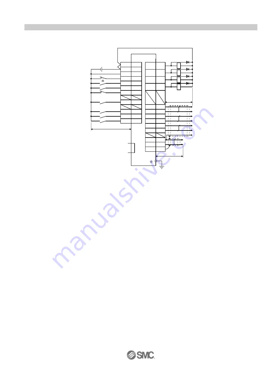
3.2.4 Positioning mode (Sink I/O interfaces)
(1) Connection example
An example of a connection for the position control mode is shown below. Connect wires as necessary.
LZ
Plate
Servo amplifier
(Note 1)
(Note 2)
T rouble (Note 6)
Electromagnetic
brake interlock
9
ALM
10
MEND
11
RD
12
MBR
(Note 7)
CN1
T ravel completion
(Note 13)
Ready
15
LA
16
LAR
17
LB
18
LBR
14
LG
21
OP
SD
10m max.
2m max.
Encoder B-phase pulse
(differential line driver)
Control common
Encoder Z-phase pulse
(open collector)
Encoder Z-phase pulse
(differential line driver)
19
20
LZR
(Note 7)
CN1
1
13
DICOM
DOCOM
10m max.
+
CN3
(Note 8)
MR Configurator
Personal
computer
24VDC
RA 1
RA2
RA3
RA4
(Note 4, 9)
(Note 9, 11)
8
4
3
7
Forced stop
Servo-on
Automatic/manual selection
Forward rotation start
Reverse rotation start
(Note 3, 5)
25
6
Proximity dog
EM1
SON
MD0
ST1
ST2
DOG
(Note 9,
10, 12)
5
DI0
23
DI1
Point table No./Program No.
selection 2
Point table No./Program No.
selection 1
CNP1
2
OPC
Control common
Encoder A-phase pulse
(differential line driver)
USB cable
(option)
When connecting the CN1-23 pin and CN1-25 pin, supply the + 24V to OPC.
Refer to
“
LECSA Operation Manual”,section 3.2 for wiring details.
Refer to
“
LECSA Operation Manual (
Simplified Edition)”,section 3.2.1 (2) and (3) for input/output signal details.
Driver


