-
9
-
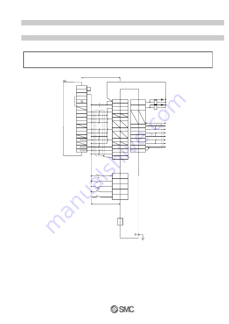
3.2 I/O signal connection example
Detail of connection examples for the I/O signals of the driver.
3.2.1 Position control mode (Sink I/O interfaces)
(1) Connection example
An example of a connection for the position control mode is shown below. Connect wires as necessary.
COM3
X
X
9
ALM
15
LA
16
LAR
17
LB
18
LBR
19
LZ
20
LZR
14
LG
SD
RD
14
11
21
23
2
25
5
1
L
N
COM2
Y000
COM1
Y004
Y010
OP
LG
PP
OPC
NP
DICOM
DOCOM
CR
13
RA 1
RA2
8
4
3
6
7
EM1
SON
RES
LSP
LSN
S/S
24V
0V
12
MBR
X
INP
10
CNP1
SD
(Note 10, 12)
T rouble (Note 6)
Electromagnetic
brake interlock
Encoder A-phase pulse
(differential line driver)
Encoder B-phase pulse
(differential line driver)
Control common
Encoder Z-phase pulse
(differential line driver)
Forward rotation
stroke end
Reverse rotation
stroke end
(Note 3, 5)
(Note 5)
(Note 10, 11)
(Note 9)
Servo-on
Reset
10m max.
(Note 1 )
USB cable
(option)
MR Configurator
CN3
Personal
computer
(Note 14)
(Note 15)
Servo amplifier
10m max.
2m max. (Note 8)
(Note 7 )
Programmable logic
controller
FX
3U
-
MT /ES (Note 13)
(Note 7 )
Plate
Plate
CN1
CN1
24VDC
(Note 4, 10 )
(Note 2 )
Forced stop
CN1
(Note 7 )
PLC power
supply
When connecting the CN1-23 pin and CN1-25 pin, supply the + 24V to OPC.
Refer to
“LECSA Operation Manual”, section 3.2 for wiring details.
Refer to
“
LECSA Operation Manual (
Simplified Edition)”,section 3.2.1 (2) and (3) for input/output signal details.
Note 1)
If the command pulse train input is open collector method, it supports only to the sink (NPN) type interface.
It does not correspond to the source (PNP) type interface.
This is a wiring example using the Mitsubishi Electric (FX3U-
□□MT/ES) PLC for position control.
(Connection example of the open collector system) See
“
LECSA Operation Manual” and the technical
data disclosed the PLC and positioning unit operation manuals.
Diver
23
Note1)
25
Note1)


