EN
15. Appendix
15
- 105 -
951-180-076-EN
Version 0y
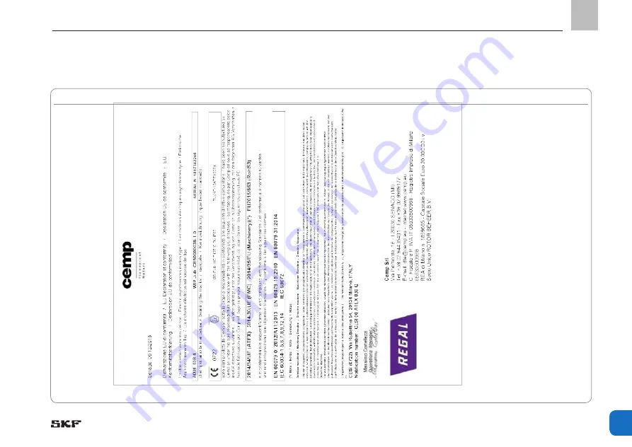
15.4 Declaration of Conformity for motor, manufacturer CAMP
Fig.45 CEMP Motor Konformitätserklärung
Страница 1: ...Version 02 951 180 076 EN EN Operating instructions according to ATEX Directive 2014 34 EU FF and FB EEX multiline pump units foh use in phoghessive centhalized lubhication systems...
Страница 2: ...1 1 3 1 3 2 1 3 4 1 5 1 1 5 6 1 5 8 1 5 9 1 6 1 1 7 1 1 7 3 1 7 4 The technical documentation pursuant to ATEX Directive 2014 34 EU Annex VIII No 2 has been prepared and filed with the conformity asse...
Страница 3: ...uture use Disclaimer of liability The manufacturer shall not be held liable for damage resulting from Improper usage assembly operation configuration maintenance repair or accidents Improper reaction...
Страница 4: ...5 Provision of personal protective gear 14 1 16 Operation 15 1 17 Emergency shutdown 15 1 18 Transport assembly maintenance malfunction repair shutdown disposal 15 1 19 Initial commissioning daily sta...
Страница 5: ...truck or forklift 51 6 Assembly 52 6 1 General information 52 6 1 1 Assembly location 53 6 2 Mechanical connection 53 6 2 1 Minimum mounting dimensions 53 6 2 2 Tightening torques 54 6 2 3 Assembly h...
Страница 6: ...trol 91 12 Repairs 92 12 1 Removing a pump element 92 12 2 Installing a pump element 93 13 Lhutdown disposal 96 13 1 Temporary shutdown 96 13 2 Permanent shutdown disassembly 96 13 3 Disposal 96 14 Lp...
Страница 7: ...ear personal protective gear face mask Wear personal protective gear gloves Wear personal protective gear protective clothing Wear personal protective gear protective footwear Unlock the product Gener...
Страница 8: ...horsepower I current intensity db A sound pressure level kp kilopound V volt greater than fpsec feet per second W watt less than Conversion factors AC alternating current plus minus Length 1 mm 0 0393...
Страница 9: ...dangers in proper technical condition and according to the information in this manual Familiarize yourself with the functions and operation of the product The speci fied assembly and operating steps...
Страница 10: ...d operating tem perature range Use of non specified equipment Use without a pressure regulating valve Use in continuous operation Use in areas with aggressive corrosive substances e g high ozone loads...
Страница 11: ...ibited 1 7 Prohibition of certain activities The following activities must be performed only by employees of the manufacturer or authorized persons due to possibly unde tectable sources of error or du...
Страница 12: ...ed documents In addition to this manual the following documents must be observed by the re spective target group Operational instructions approval rules The safety data sheet of the lubricant used If...
Страница 13: ...n Germany 15 C Ta 40 C EX 1 12 Note on CE marking The CE marking is based on the require ments of the applied Directives 2014 34 EU ATEX Directive 2014 30 EU Electromagnetic compatibility Note on Low...
Страница 14: ...rson competent due to qualified technical education training and experience to recognize risks and possible hazards when working on the device or sub components in potentially explosive atmo spheres a...
Страница 15: ...gh tem peratures e g altered flow properties of the lubricant Maintenance and repair work should therefore preferably be per formed at room temperature Prior to performing work the product and the mac...
Страница 16: ...a calibrated torque wrench when tightening Establish the electrical connection only in accordance with the valid circuit diagram and in observance of the relevant regula tions and the local electrical...
Страница 17: ...missing warning labels are immediately replaced 1 20 Cleaning There is a fire hazard from the use of flammable cleaning agents Use only non flammable cleaning agents that are suitable for the intende...
Страница 18: ...k in potentially explosive atmo spheres Unauthorized persons must be kept away There must be no evidence that parts of the explosion protection are missing or non functional If this is not excluded sw...
Страница 19: ...ulated dust Accumulated dust has a thermal insulating effect and promotes the formation of a potentially explosive atmosphere when agitated swirled The product must be integrated into the operator s l...
Страница 20: ...tially explosive atmospheres Operation is only permitted in compliance with All information within this manual and the information within the referenced documents All laws and regulations that the ope...
Страница 21: ...5 2 Explosion protection measures Based on a comprehensive assessment of the work area the operator ensures that the equipment and all installation materials are suitable for operation in potentially...
Страница 22: ...lity using practical exercises The instruction includes at least Zone classification Scope and limits of the area of activ ity and responsibility for the respective group of people Safety conscious be...
Страница 23: ...class 8 8 Personal injury property damage due to electric shock resulting from power lead damage B C D E F G H Inspect power leads for damage prior to initial use and then at regular intervals Do not...
Страница 24: ...gnition temperature range by an undetected malfunction within the centralized lubrication system C D G The operator must critically examine whether operation without corresponding detection options re...
Страница 25: ...isolating amplifiers for example to oper ate a capacity sensor in the potentially explo sive atmosphere C D G Install isolating amplifiers only outside of the potentially explosive atmosphere Incorrec...
Страница 26: ...achine and forms the basis for plan ning the centralized lubrication system The manufacturer operator of the machine should preferably make the selection with the supplier of the lubricant on the basi...
Страница 27: ...downtime check before re commissioning that the lubricant is still suitable for use in terms of chemical and physical signs of aging We recommend performing this inspection after one week of machine d...
Страница 28: ...3 Lubricant reservoir 4 Grease follower plate 5 Agitator 6 Pump element with ring piece second row pump elements 13 to 24 7 Pump element with ring piece first row pump elements 1 to 12 8 Filler socke...
Страница 29: ...able in designs with a delivery piston diameter of 6 8 or 10 mm The delivery rate range is 0 03 to 0 23 cm3 at a maximum operating pressure of 350 200 or 125 bar The lubricant reservoir 3 is available...
Страница 30: ...he outlet Once the pressure stroke is complete the suction stroke of the delivery piston 1 begins Moving the delivery piston 1 also brings the control piston 3 back to its normal position using spring...
Страница 31: ...onal description Chamber A Chamber B Legend to Fig 3 Item Deschiption 1 Delivery piston 2 Screw in cylinder 3 Spring loaded control piston 4 Adjustment cap 5 Ring piece with check valve 6 Cap nut 7 Pr...
Страница 32: ...m3 stroke Operating pressure of pump units Piston 6 Max 350 bar Piston 10 Max 125 bar Piston 8 Max 200 bar Feedable lubricants 1 Mineral oils base oils or environmentally compatible oils from ISO VG 4...
Страница 33: ...to thmee phase motoms fmom VEM othem specifications available on mequest Motoh design 230 V AC 400 V AC 50 Hz Motoh type Three phrase motors with squirrel cage rotor Standard Efficiency IE1 or Premium...
Страница 34: ...nB B cos B IB IA IB m Fhame size flange ATEX DMT 00 ATEX E 012 X kW Nm m 1 IEC EN60034 30 1 400V kg 100 75 50 A IEC C 1M IE1 KPER 63 K6 Ex II 2D 0 09 0 96 895 IE1 50 4 46 2 38 4 0 56 0 46 2 5 4 9 63...
Страница 35: ...xplosion protection marking II 2D Ex tb IIIC T125 C Db Protection type tb dust Type IM B14 Protection type t Device protection level b Flange See the following motor tables Insulation class F Ambient...
Страница 36: ...to EN 60079 31 Explosion protection marking II 2D Ex tb IIICT125 C Db Protection type t Device protection level b Type IM B14K Flange See the following motor tables Insulation class F 155 Continuous o...
Страница 37: ...I 2D Ex tb IIICT135 C Db Protection type t Device protection level b Type B14 surface cooling IC411 Max surface temperature T 135 C Flansch See the following motor tables Insulation class F Continuous...
Страница 38: ...d Efficiency IE1 or Premium Efficiency IE3 motors for use in zone 1 acc to EN 60079 1 Explosion protection marking II 2G Ex d de IIC T4 Gb Explosion proof enclo sure d increased safety e high protecti...
Страница 39: ...0 hpm Design 4 pole Premium Efficiency IE3 Manufacturer VEM Design ATEX type P MB nB B cos B IB IA IB m Fhame size flange ATEX PTB 09 ATEX 1017 X kW Nm m 1 at 400V kg A IEC C 1M K82R 63 MX4 Ex de IIC...
Страница 40: ...0 600 1 750 Note The displacements shown are based on the motors rated speeds At reduced speeds see rating plate the values are lowered accordingly The characteristics of lubricants such as operating...
Страница 41: ...nominal volume F Piston diameter 6 mm 00 0 12 12 04 4 kg G Piston diameter 8 mm 00 0 12 12 10 10 kg H Piston diameter 10 mm 00 0 12 12 C Type of fill level monitoring K Connection for pump elements F...
Страница 42: ...for drive position G max 23 Displacement of pump elements Piston 6 Piston 10 0 027 0 077 up to 0 08 cm3 stroke up to 0 23 cm3 stroke Piston 8 0 050 to 0 15 cm3 stroke Operating pressure of pump units...
Страница 43: ...iciency IE1 or Premium Efficiency IE3 motors for use in zone 21 acc to EN 60079 31 Explosion protection marking II 2D Ex tb IIIC T125 C Db Protection type t Device protection level b Type IM V18 B14 w...
Страница 44: ...oh design 1M 2M See rating plate This data mefems to thmee phase motoms fmom VEM othem specifications available on mequest Motoh design 230 V AC 400 V AC 50 Hz Motoh type Three phrase motors with squi...
Страница 45: ...4 0 25 1 7 1370 68 5 0 80 0 66 3 9 16 71 105 SKF item numbeh 84 5511 4802 2M K82R 71 MX4 Ex de IIC T4 0 37 2 6 1380 71 0 80 0 94 3 9 17 71 105 SKF item numbeh 84 5511 4803 Rated speed 1000 hpm Design...
Страница 46: ...er pump element cm min Rated speed rpm Displacement as a function of 8 mm piston diameter Volumetric flow per pump element cm min Rated speed rpm Displacement as a function of 10 mm piston diameter Vo...
Страница 47: ...ervoir design s nominal volume G Piston diameter 6 mm 00 0 24 24 06 6 kg 15 15 kg H Piston diameter 8 mm 00 0 24 24 30 30 kg K Piston diameter 10 mm 00 0 24 24 C Type of fill level monitoring L Connec...
Страница 48: ...of return shipments 5 3 Ltorage Before usage check products for damage that may have occurred during storage This applies in particular to parts made of plas tic and rubber due to embrittle ments as w...
Страница 49: ...10 per year WARNING The permissible load capacity of the customer provided lift ing equipment lifting lugs lifting ropes cranes forklifts etc may not be below the total weight of the multiline pump un...
Страница 50: ...of the lubricant medium See the Technical data chapter or the shipping documents for the total weight of the multiline pump unit In case the multiline pump is filled calculate the total weight Add a 2...
Страница 51: ...atchet straps etc must be designed for the total weight of the multiline lubrication pump a 20 safety margin The customer must secure assemble the lifting equipment in accordance with its re spective...
Страница 52: ...prevention Any visual monitoring equipment pres ent such as pressure gauges min max markings oil sight glasses piston detec tors etc must be clearly visible Follow the mounting position require ments...
Страница 53: ...1 Assembly location The product should to the extent possible be protected from humidity and vibration and should be mounted so that it is easily accessible This facilitates further installa tion ins...
Страница 54: ...5 Drill assembly holes M10 acc to the as sembly drawings Fig 7 8 and the condi tions on the surface Clean surface to remove drilling chips Place the pump unit on the surface and roughly align it Pass...
Страница 55: ...x Hole circle 236 mm 120 40 00 FF FB 1M E 204 40 59 00 102 20 177 00 FB 2M H FB 1M B 11 204 40 102 20 177 00 59 00 11 3x Hole circle 236 mm 236 1 4 30 395 190 50 FB 1M A 39014 236 30 190 FB 1M G 505 2...
Страница 56: ...2 1 9 10 12 11 3x bore 11 Hole circle 236 Filler socket Layout of Pump elements 10 kg reservoir 4 kg reservoir Cleoronce divensions without fill level switch Reservoir copocity A B C D kg vv 4 kg 270...
Страница 57: ...cket G 3 8 3x bore 11 Hole circle 236 Filler socket Layout of Pump elements Cleoronce divensions without fill level switch Reservoir copocity A B C D kg vv 4 kg 235 100 550 10 kg 750 Note Clearance di...
Страница 58: ...ghease applications Resehvoih capacity 4 kg 10 kg Dimensions mm A B A B Fill level control E 185 250 390 450 Fill level control F 190 260 390 450 Fill level control H 195 330 390 525 Fill level contro...
Страница 59: ...0 11 12 19 20 21 22 23 24 30 2 row 13 to 24 1 row 1 to 12 Filler socket Filler socket G 3 8 Layout of Pump elements 30 kg reservoir 15 kg reservoir Cleoronce divensions without fill level switch Reser...
Страница 60: ...50 82 113 24 B D C A E 2 row 13 to 24 1 row 1 to 12 Filler socket Filler socket G 1 2 Layout of Pump elements 30 kg reservoir 15 kg reservoir Cleoronce divensions without fill level switch Reservoir...
Страница 61: ...12 19 20 21 22 23 24 30 B Layout of pump elements 2 row 13 to 24 1 row 1 to 12 6 kg reservoir 15 kg reservoir Filler socket G 1 2 Filler socket Cleoronce divensions without fill level switch Reservoir...
Страница 62: ...19 20 21 22 23 24 B Layout of pump elements 2nd row 13 to 24 1st row 1 to 12 6 kg reservoir 15 kg reservoir Filler socket G 1 2 Filler socket Cleoronce divensions without fill level switch Reservoir c...
Страница 63: ...2 23 24 B 2nd row 13 to 24 1st row 1 to 12 6 kg reservoir 30 kg reservoir 15 kg reservoir Filler socket G 1 2 Filler socket Layout of pump elements Cleoronce divensions without fill level switch Reser...
Страница 64: ...15 kg 30 kg Dimensions mm A B A B A B Fill level control E 170 230 375 430 320 380 Fill level control F 170 230 375 430 330 390 Fill level control H 190 315 430 550 325 455 Fill level control G 200 24...
Страница 65: ...tinuously safe electrical connection no protruding wire ends use the assigned cable end fittings e g cable lugs wire end ferrules Select connecting cables conforming to DIN VDE 0100 taking into accoun...
Страница 66: ...the manufactur er s operating instructions The informa tion contained therein must be observed 1 WARNING Dovoge to puvp votor puvp When establishing the electrical connection of the pump motor be mind...
Страница 67: ...otor s operating instructions Mark the terminal diagram used on the motor data sheet and enclose the motor data sheet with these operating instructions Secure the multiline pump unit using a motor cir...
Страница 68: ...vided by customer 1 3 2 4 5 1 2 3 4 5 Loosen the clamping screw 2 on the ground terminal 1 Insert the cable end of the standard grounding cable 3 into the ground terminal Tighten the clamping screw 2...
Страница 69: ...fill levels controls must be supplied by an intrinsically safe circuit e g through the installation of an ATEX compliant isolating amplifier by the customer When selecting the isolating amplifier keep...
Страница 70: ...on class IP 65 6 7 1 Fill level control E 3 4 2 1 Switch position at minimum Switch position above minimum 3 4 2 1 Lo must be greater than Lc Li and Co must be greater than Cc Ci Keep in mind that the...
Страница 71: ...urrent Ii 100 mA Capacitance Ci 1 nF Inductance Li 5 H Connection diagram Plug EN 175301 803 DIN 43650 Protection class IP 65 6 7 2 Fill level control F Switch position at minimum 3 4 2 1 Switch posit...
Страница 72: ...witch position at minimum Switch position at pre warning Switch position at maximum Switch position at minimum Switch position at pre warning Contact II Contact I Contact III Switch position between t...
Страница 73: ...l H Design Reed contact with three switching points maximum minimum pre warning minimum Form of contact NC contact NO contact Voltage Ui 30 V DC Current Ii 100 mA Capacitance Ci 1 nF Inductance Li 5 H...
Страница 74: ...G Ex ia IIC T6 Ga Ta 20 70 C II 1G Ex ia IIC T5 Ga Ta 20 80 C II 1D Ex ia IIIC T90 C Da Ta 20 70 C II 1D Ex ia IIIC T100 C Da Ta 20 80 C Sensing distance 4 mm cannot be mounted flush Effective sensing...
Страница 75: ...ontact NO contact NO contact rising Connection housing Aluminum 80 x 75 x 57 mm Material Thread contact pipe float switches 1 4435 Level contact Bistable reed contact Max operating pressure 1 bar Igni...
Страница 76: ...s pay careful attention to the assembly instructions and technical specifications provided by the manufacturer Secure the centralized lubrication system against excessive pres sure using an appropriat...
Страница 77: ...n the union nut 2 by hand Tighten the union nut 2 with an open end wrench 1 2 3 4 6 8 1 Assembly of the lubrication lines Legend to Fig 21 Item Deschiption 1 Lubrication line to match pipe connection...
Страница 78: ...itted properly in place Switch on the multiline pump unit briefly for about 1 sec and check the direction of rotation Fit the reservoir cover 1 with grease fol lower plate 2 back on the reservoir 3 Ac...
Страница 79: ...setting sleeve 7 When adjusting Clockwise rototion results in de creased displacement counterclockwise rototion results in increased displacement The pump element s displacement may be reduced to 1 3...
Страница 80: ...of the pump without lubricant is prohibited as this may lead to heating of the bearings The pump s lubricant reservoir must be filled with suitable lubricant at regu lar and appropriate intervals Expl...
Страница 81: ...Remove the filling hose Remove the equipotential bonding con nection between the filling pump and the multiline pump unit Filler socket FB G 1 2 Filler socket FF G 3 8 Only fill using clean lubricant...
Страница 82: ...nt is fully reinstalled and functional Grounding fully present properly connected and electrically continuous Equipotential bonding fully present properly connected and electrically continuous No accu...
Страница 83: ...quency converter is not permitted SKF products operate largely automatically The activities required during normal op eration are limited primarily to inspection of the fill level timely refilling of...
Страница 84: ...accordance with the IP protection class of the pump Otherwise electrical components may be damaged Cleaning required personal protective gear cleaning agents and equipment are in accordance with the c...
Страница 85: ...eplaced if necessary When removing and installing individual pump elements proceed as described in the chapter Repair Careful and regular maintenance is required in order to detect and remedy possibly...
Страница 86: ...contamination or corrosion Any dismantled protective and monitoring equipment is fully reinstalled and functional All warning labels on the product are present and in proper condition No unusual noise...
Страница 87: ...ary according to the climatic conditions at the place of use X X X Check the motor fixing bolts for tightness X Check the terminal box fixing bolts for tightness X With motor running Electrical charac...
Страница 88: ...l the gearbox with new gear oil up to the lower edge of the screw plug Gearbox Maintenance work Operating hours Bh Perform visual inspection First time after approx 50 Bh Every 1000 oh or once annuall...
Страница 89: ...d is too low Check electrical connections and voltage Remove foreign substances if agitator or pump element is jammed Replace the defective motor if necessary No delivery with pipe con nections and su...
Страница 90: ...pty and clean lubricant reservoir Remove and clean pump element with ring piece Vent and fill according to Chapter 7 Initial commissioning Woodruff key on the drive shaft is defective Replace the wood...
Страница 91: ...Signal max ignored Seal on the grease follower plate is leaking Check the cable connection replace plug or cable if necessary Remove the excess grease Replace the seal No signal from the fill level c...
Страница 92: ...he ring piece 2 Loosen the cap nut 5 and pull off the ring piece 2 Loosen and remove the screw socket 3 Carefully unscrew and remove the screw in cylinder 4 from the pump housing Tilt the front part o...
Страница 93: ...p element that you wish to install into its individual components delivery piston 1 screw in cylinder 2 screw socket 3 ring piece with check valve 4 cap nut 5 and pressure regulating valve 6 Fill the...
Страница 94: ...Tightening torque for screw in cylinder 2 See tightening torque table Screw the screw socket 3 into the screw in cylinder 2 and tighten it Tightening torque for screw socket 3 See tightening torque ta...
Страница 95: ...12 Repairs 2 3 7 5 3 4 6 9 1 2 4 5 Fitting mandrel Hexagon socket screw key 1 2 7 5 3 Pump housing 6 Cylinder chamber Fig 32 Puvp elevent disossevbly Fig 33 Screw in cylinder instollotion Fig 34 Inst...
Страница 96: ...sposal of prod ucts contaminated with lubricant must be performed by a recognized waste disposal company in compliance with environmental protection requirements and waste disposal regulations as well...
Страница 97: ...pressure bar Weight kg Pcs Item number Pressure regulating valve 50 0 13 1 24 2103 2273 100 24 2103 2344 125 24 2103 2345 150 24 2103 2342 175 24 2103 2272 200 24 2103 2346 300 24 2103 2271 14 2 Pump...
Страница 98: ...sur face with copper Cu sealing ring in place of a pump element to recirculate grease into pump housing 0 026 1 24 1755 2003 20 M20x1 5 G 1 4 14 5 Fill level control complete reservoir kit The fill le...
Страница 99: ...0 24 0254 2757 15 24 0254 2841 30 24 0254 2787 G 4 24 0254 2710 6 24 0254 2876 10 24 0254 2860 15 24 0254 2874 H 4 24 0254 2700 10 24 0254 2718 30 24 0254 2829 J 30 24 0254 2626 S W 30 24 0254 2785 Ot...
Страница 100: ...EN 15 Appendix 100 951 180 076 EN Version 0y 15 Appendix 15 1 Declaration of Conformity for motor manufacturer VEM Fig 40 VEM Declaration of Conformity page 1...
Страница 101: ...EN 15 Appendix 15 101 951 180 076 EN Version 0y Fig 41 VEM Declaration of Conformity page 2...
Страница 102: ...EN 15 Appendix 102 951 180 076 EN Version 0y Fig 42 VEM Declaration of Conformity page 3...
Страница 103: ...ement II 2D EN 60034 1 5 6 7 8 9 12 14 e g a u q r a M g n i k r a M g n u n h c i e z n n e K 0044 II 2G Ex d IIC T3 T6 Gb bzw Ex de IIC T3 T6 Gb PTB 08 ATEX 1045 X oder wahlweise or optional ou au c...
Страница 104: ...EN 15 Appendix 104 951 180 076 EN Version 0y 15 3 Declaration of Conformity for motor manufacturer Liemens Fig 44 Siemens Declaration of Conformity...
Страница 105: ...EN 15 Appendix 15 105 951 180 076 EN Version 0y 15 4 Declaration of Conformity for motor manufacturer CAMP Fig 45 CEMP Motor Konformit tserkl rung...
Страница 106: ...EN 15 Appendix 106 951 180 076 EN Version 0y 15 5 Declaration of Conformity for fill level control W Fig 46 KSR K bler Declaration of Conformity...
Страница 107: ...m 20 04 2016 2014 30 EU 2014 34 EU The following standard s was were applied Nous confirmons la conformite aux exigences essentielles de la des directive s europeenne s valable s jusqu au 19 04 2016 2...
Страница 108: ...180 076 EN Version 0y 15 7 Associated supplier documentation Associated supplier docuventotion stondord design Supplied part Manufacturer Documentation type Documentation number version number Motor...
Страница 109: ...EN 15 Appendix 15 109 951 180 076 EN Version 0y Associoted supplier docuventotion for custover specific design Supplied part Manufacturer Documentation type Documentation number version number...
Страница 110: ...cember 2019 Version 02 SKF Lubrication Systems Germany GmbH Walldorf Plant Heinrich Hertz Stra e 2 8 DE 69190 Walldorf Tel 49 0 6227 33 0 Fax 49 0 6227 33 259 E mail Lubrication germany skf com www sk...