background image

Setting options

• 3RW5 HMI High Feature

Menu: "Parameters > Soft Starter > Outputs"
Access protection to the 3RW5 HMI High Feature is not active or has been reset.

• With SIRIUS Soft Starter ES (TIA Portal) via the local interface on the 3RW5 HMI High Feature

Brief overview: Window "Project Navigation" with current project under created Soft Starter > 
"Parameters" > Window "Work area" > "Soft Starter > Outputs > Soft Starter"

• With a fieldbus via a 3RW5 communication module:

– With SIRIUS Soft Starter ES (TIA Portal) Premium / Professional (only via a 3RW5 PROFINET 

or PROFIBUS communication module)
Brief overview: See SIRIUS Soft Starter ES (TIA Portal) via the local interface on the 
3RW5 HMI High Feature

– Configuration software of the control system (e.g. STEP 7 with corresponding HSP)

– User program

You can find additional information on the parameters that can be set via the fieldbus in the 
manual of the respective 3RW5 communication module.

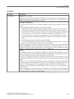
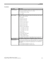
Parameter - Delay

Parameters

Description

ON delay time

The switching of the output is delayed by this time.
• Factory setting: 0 s
• Setting range: 0 ... 6 500 s
• In steps of: 0.1 s

OFF delay time

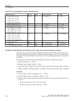
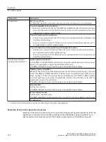
Parameter - Output action

Output action

Description

Factory setting

DQ1

DQ2 DQ3

1)

DQ4

2)

No action

-

-

x

-

x

Activation by external control sources
Control source PIQ-DQ-1.0 output 1

The control command "Output 1" is assigned to the 
corresponding digital output.
Refer to chapter Control via 3RW5 HMI High Fea‐
ture (P
age 232).

-

-

-

-

Control source PIQ-DQ-1.1 output 2

The control command "Output 2" is assigned to the 
corresponding digital output.
Refer to chapter Control via 3RW5 HMI High Fea‐
ture
 (Page 232).

-

-

-

-

Control source PIQ-DQ-2.0 output 3

3)

The control command "Output 3" is assigned to the 
corresponding digital output.
Refer to chapter Control via 3RW5 HMI High Fea‐
ture (P
age 232).

-

-

-

-

Control source input 1

Digital output is activated by "Digital input 1".

-

-

-

-

Functions
8.13 Outputs

SIRIUS 3RW55 and 3RW55 Failsafe Soft Starters

200

Equipment Manual, 02/2022, A5E35630887002A/RS-AF/006

Содержание SIRIUS 3RW55

Страница 1: ... 2022 A5E35630887002A RS AF 006 Siemens Industry Online Support 1 Safety information 2 Description 3 Mounting and dismantling 4 Connecting 5 Parameter assignment 6 Commissioning 7 Functions 8 Messages and diagnostics 9 Maintenance and service 10 Technical specifications 11 Dimension drawings 12 Circuit diagrams 13 Example circuits A ...

Страница 2: ...based on their training and experience are capable of identifying risks and avoiding potential hazards when working with these products systems Proper use of Siemens products Note the following WARNING Siemens products may only be used for the applications described in the catalog and in the relevant technical documentation If products and components from other manufacturers are used these must be...

Страница 3: ... Recycling and disposal 22 3 Description 23 3 1 History 23 3 2 Hardware configuration 24 3 3 Operating principle 25 3 4 3RW5 HMI High Feature 28 3 5 Options for accessing the 3RW55 and 3RW55 Failsafe soft starters 30 3 6 Operating modes and master control function 32 3 6 1 Operating modes 32 3 6 2 Sets the operating mode 35 3 7 Device versions 39 3 8 Areas of application and load types 43 3 9 Sele...

Страница 4: ...5 6 Replacement of the box terminal blocks with size 2 78 5 7 Connecting the control terminals screw terminals 80 5 8 Disconnecting the control current form the screw type terminals 81 5 9 Connecting the control terminals spring type terminals 82 5 10 Disconnecting the control current from the spring loaded terminals 83 5 11 Replacing the control terminals 84 5 12 Installing the cover for the cont...

Страница 5: ...rtup functions 144 8 2 Run down 146 8 2 1 Stopping modes 146 8 2 2 Coasting down 148 8 2 3 Voltage ramp 149 8 2 4 Torque control 150 8 2 5 Pump stop 152 8 2 6 DC braking 154 8 2 6 1 DC braking with external braking contactors 154 8 2 6 2 Dynamic DC braking without contactor 157 8 2 6 3 Reversing DC braking with a reversing contactor assembly 160 8 2 6 4 Sensorless motor standstill detection 162 8 ...

Страница 6: ...ng 227 8 20 1 Monitoring the measured values of the 3RW55 soft starter with the 3RW5 HMI High Feature 227 8 20 2 Graphical display of measured values on the 3RW5 HMI High Feature 229 8 20 3 Monitoring the process image of the 3RW55 soft starter with the 3RW5 HMI High Feature 231 8 21 Control via 3RW5 HMI High Feature 232 8 22 Overview 234 8 23 Local access protection and user account administratio...

Страница 7: ...9 10 3 Firmware update 275 10 4 Performing firmware update with micro SD card 3RW5 HMI High Feature 277 10 5 Restoring factory setting 278 10 5 1 Restoring the factory settings via High Feature 3RW5 HMI 279 10 5 2 Restoring the factory settings with the Master RESET button via 3RW5 HMI High Feature 280 10 6 Device change function 281 10 6 1 Device change with micro SD card on the 3RW5 HMI High Fea...

Страница 8: ... 322 A 3 8 3RW55 soft starter for serial starting with 3 parameter sets 323 A 3 9 Soft starter for pole changing motor with separate windings and 2 parameter sets 328 A 3 10 3RW55 soft starter with direct on line starting DOL as emergency start 330 A 3 11 Starting a Dahlander motor 331 A 3 12 External bypass 334 A 3 13 EMERGENCY STOP shutdown to SIL 1 or PL c with a 3SK1 safety relay without the 3...

Страница 9: ...ble Certificates Clearly sorted according to approving authority type and country Characteristics For support in planning and configuring your system Product announcements The latest information and news concerning our products Downloads Here you will find updates service packs HSPs and much more for your product Application examples Function blocks background and system descriptions performance s...

Страница 10: ...ur entire automation project My documentation Configure your individual documentation from different manuals CAx data Easy access to CAx data e g 3D models 2D dimension drawings EPLAN macros device circuit diagrams My IBase registrations Register your Siemens products systems and software Siemens Industry Online Support app The Siemens Industry Online Support app provides you access to all the dev...

Страница 11: ...09753752 Equipment Manuals for the 3RW5 soft starter https support industry siemens com cs ww en ps 16212 man Equipment Manual for the 3RW5 PROFINET communication modules https support industry siemens com cs ww en view 109753754 Equipment Manual for the 3RW5 PROFIBUS communication module https support industry siemens com cs ww en view 109753753 Equipment Manual for the 3RW5 Modbus communication ...

Страница 12: ...ds for soft starters 3RW5 https support industry siemens com cs ww en ps 16212 dl Catalog IC 10 https support industry siemens com cs ww en view 109747945 Product support for STEP 7 TIA Portal https support industry siemens com cs ww en ps 14672 Siemens Industry Online Support 1 2 Additional documentation SIRIUS 3RW55 and 3RW55 Failsafe Soft Starters 12 Equipment Manual 02 2022 A5E35630887002A RS ...

Страница 13: ...shold of human perception These static voltages develop when you touch a component or electrical connection of a device without having drained the static charges present on your body The damage caused to a device by overvoltage is usually not immediately evident and is only noticed after an extended period of operation Electrostatic charging Anyone who is not connected to the electrical potential ...

Страница 14: ...Do so by touching grounded metallic parts Use only grounded measuring instruments 2 2 Five safety rules for working in or on electrical systems A set of rules which are summarized in DIN VDE 0105 as the five safety rules are defined for working in or on electrical systems as a preventative measure against electrical accidents 1 Isolate 2 Secure against re connection 3 Verify absence of operating v...

Страница 15: ...ted around them to avoid accidental contact during the work with adjacent parts that are still live 2 3 Reactive power compensation Capacitors for improving the power factor reactive power compensation Do not connect any capacitors to the output terminals of the 3RW5 soft starter If capacitors are connected to the output terminals the 3RW5 soft starter will be damaged Do not operate active filters...

Страница 16: ...applied as soon as they are available and that the latest product versions are used Use of product versions that are no longer supported and failure to apply the latest updates may increase customer s exposure to cyber threats To stay informed about product updates subscribe to the Siemens Industrial Security RSS Feed under https www siemens com cert 2 6 ATEX IECEx 2 6 1 Use in Class I and Class I...

Страница 17: ...the 3RW55 or 3RW55 Failsafe soft starters to the rated operational current of the motor as stated on the type plate or design test certificate of the motor Trip class electronic overload protection Make sure that the motor and the cables are dimensioned for the selected trip class The rated data of the 3RW55 and 3RW55 Failsafe soft starters refers to normal starting CLASS 10E For heavy starting CL...

Страница 18: ...g commissioning and periodically at intervals of no more than 36 months Certification of the 3RW55 and 3RW55 Failsafe soft starters Note Firmware versions and product versions of the 3RW55 soft starter with ATEX IECEx certification For 3RW55 soft starters certified motor overload protection according to ATEX IECEx is only provided from firmware version V2 0 and product version E02 does not apply t...

Страница 19: ... outputs 95 96 and 98 output 3 You will find more information in chapter Connecting Page 71 The motor connection type Automatic detection is not approved for ATEX IECEx applications Type of motor connection Inside delta Note that operation of a 3RW55 or 3RW55 Failsafe soft starter with motor connection type Inside delta without implementing one of the two following remedial measures results in los...

Страница 20: ...oration of the factory setting of the 3RW55 or 3RW55 Failsafe soft starter in active Ex operation is only permissible via the master RESET button on the 3RW5 HMI High Feature This resets the parameters of the 3RW55 and 3RW55 Failsafe soft starters to the factory settings After restoration of the factory settings you have to parameterize the 3RW55 and 3RW55 Failsafe soft starters again for use in C...

Страница 21: ...e 1 The 3RW55 Failsafe soft starter is defective after a short circuit Replace the defective 3RW55 Failsafe soft starter Short circuit protection for coordination type 2 The 3RW55 Failsafe soft starter is still fully functional after a short circuit Run the self test user test Page 264 to check the safety function before continuing to use the 3RW55 Failsafe soft starter Note Function test In conti...

Страница 22: ...fe soft starters without any problem and with their full range of functions ensure that all components have the latest firmware Page 275 3RW55 and 3RW55 Failsafe soft starters 3RW5 HMI High Feature 3RW5 communication module accessory You will find current downloads and a history of the versions with new features on the 3RW5 topic page https support industry siemens com cs ww en view 109747404 2 10...

Страница 23: ...l 03 2019 Revision of the manual Addition of functions for the 3RW55 soft starter e g test with small load reversing DC brake simulation 3RW55 soft starter size 5 ATEX IECEx certified motor overload protection 11 2019 Revision of the manual Addition of functions for the 3RW55 soft starter e g emergency run function 3RW55 Failsafe soft starter 04 2020 Revision of the manual Addition of functions fo...

Страница 24: ...3RW5 communication module accessory Connectable conductor cross sections You will also find the conductor cross sections that can be connected in the Technical specifica tions Page 285 Main circuit connection motor Control terminals inputs outputs Control cable duct with cover Description 3 2 Hardware configuration SIRIUS 3RW55 and 3RW55 Failsafe Soft Starters 24 Equipment Manual 02 2022 A5E356308...

Страница 25: ...RW55 and 3RW55 Failsafe soft starters start the motor as soon as the switch on command is issued t1 During the ramp up time t1 to t3 the current is conducted via power semiconductors switching elements which start the motor smoothly The 3RW55 and 3RW55 Failsafe soft starters feature internal start up recognition If the 3RW55 or 3RW55 Failsafe soft starter detects a motor start up before the ramp u...

Страница 26: ...5 and 3RW55 Failsafe soft starters Note the information in chapter Firmware update Page 22 Parameterizable soft starting for a smooth drive start up Parameterizable soft stopping for a smooth drive stop Parameterizable current limiting for avoiding current peaks Integrated electronic motor overload protection with adjustable trip class OFF CLASS 10A 10E 20E 30E Integrated intrinsic device protecti...

Страница 27: ...anical loads and optimum control of pump stopping Breakaway pulse for overcoming high stiction e g in mills Access protection by PIN and user accounts Micro SD card for saving data Optional 3RW5 communication module for integration into bus systems PROFIenergy Energy saving functions due to stand by mode and energy saving while idle for 3RW55 soft starters from firmware version V2 1 and 3RW55 Fail...

Страница 28: ... all of the functions of the 3RW5 soft starter in the Catalog IC 10 https support industry siemens com cs ww en view 109747945 You will find further details of the functions in chapter Functions Page 129 3 4 3RW5 HMI High Feature You can use the 3RW5 HMI High Feature to parameterize monitor and control the 3RW55 and 3RW55 Failsafe soft starters You can remove the 3RW5 HMI High Feature from the 3RW...

Страница 29: ...dress and other communication parameters EtherNet IP IP parameters and other communication parameters Backup of parameterization data on a micro SD card The display of the device LEDs of the 3RW5 HMI High Feature shows the messages of the following devices 3RW55 or 3RW55 Failsafe soft starter 3RW5 HMI High Feature Communication module if there is one Firmware updates can be performed using the 3RW...

Страница 30: ... the controller e g STEP 7 Programmable logic controller e g SIMATIC S7 1500 Fieldbus via optional 3RW5 communication module PC with SIRIUS Soft Starter ES TIA Portal Premium Professional via an optional 3RW5 PROFINET or PROFIBUS communication module Motor PC with SIRIUS Soft Starter ES TIA Portal via local interface on 3RW5 HMI High Feature Options for data transfer Monitoring Diagnosis Control P...

Страница 31: ...ia a 3RW5 PROFINET or PROFIBUS communication module 2 Only via an optional 3RW5 PROFINET High Feature communication module from firmware version V2 0 3 Login necessary with Operating personnel or Service personnel user role Description 3 5 Options for accessing the 3RW55 and 3RW55 Failsafe soft starters SIRIUS 3RW55 and 3RW55 Failsafe Soft Starters Equipment Manual 02 2022 A5E35630887002A RS AF 00...

Страница 32: ...ation module from firmware ver sion V2 0 Control source PLC operating mode Automatic Control source Modbus client or Modbus master operating mode Automatic Control source SIRIUS Soft Starter ES TIA Portal Premium Professional operating mode Man ual operation bus PC controlled Control source Digital inputs operating mode Manual operation local Input controlled or Au tomatic operation Input controll...

Страница 33: ...55 Failsafe soft starter via the 3RW5 communication module In operating mode Manual bus a control source on the fieldbus has master control SIRIUS Soft Starter ES TIA Portal Premium Professional Web server in combination with 3RW5 PROFINET High Feature communication module from firmware version V2 0 Operating mode Manual local In operating mode Manual local master control is with a control source ...

Страница 34: ...fe soft starters behave as set in the parameter Response to CPU Master Stop irrespective of the mode If other connections between the control source and 3RW55 or 3RW55 Failsafe soft starter are aborted master control automatically switches back to the lowest priority of the current operating mode Automatic mode The 3RW55 and 3RW55 Failsafe soft starters behave as set in the parameter Response to C...

Страница 35: ...rview Window Task Card Tab Online Tools SIRIUS Control Panel Master Control Release Control Command in the web server Web page Control Panel Master Control Release Control If the input action Operating mode manual local is parameterized By deactivating the input action Operating mode manual local If the input action Operating mode manual local is not parameterized By deactivating the Manual operat...

Страница 36: ...withdrawn from the operating mode Manual operation bus PC controlled by the operating mode Manual local as follows If the input action Operating mode manual local is not parameterized By activating the Manual operation local Input controlled bit in the process image output PIQ or in the data table Process image output PIQ depending on the 3RW5 communication module If the input action Operating mod...

Страница 37: ...igital inputs receive control from Automatic mode or operating mode Manual bus as follows If the input action Operating mode manual local is not parameterized By activating the Manual operation local Input controlled bit in the process image output PIQ or in the data table Process image output PIQ depending on the 3RW5 communication module If the input action Operating mode manual local is paramet...

Страница 38: ...l interface on the 3RW5 HMI High Feature Brief overview Window Task Card Tab Online Tools SIRIUS Control Panel Master Control Get Control Operating mode Manual operation local HMI controlled Fetching control The 3RW5 HMI High Feature actively fetches control with the action LOCAL REMOTE from the lower priority control source If control is with the local interface on the 3RW5 HMI High Feature highe...

Страница 39: ...in the 3RW55 or 3RW55 Failsafe soft starter master control is given back to the digital inputs Brief overview Window Task Card Tab Online Tools SIRIUS Control Panel Master Control Release Control Withdrawal of control by other control sources Control cannot be withdrawn from SIRIUS Soft Starter ES TIA Portal by any control source Additional information You will find more information on the process...

Страница 40: ...3RW55 3RW55 Failsafe Size 3 3RW55 3RW55 Failsafe Size 4 3RW55 3RW55 Failsafe Description 3 7 Device versions SIRIUS 3RW55 and 3RW55 Failsafe Soft Starters 40 Equipment Manual 02 2022 A5E35630887002A RS AF 006 ...

Страница 41: ...Size 5 3RW55 3RW55 Failsafe Description 3 7 Device versions SIRIUS 3RW55 and 3RW55 Failsafe Soft Starters Equipment Manual 02 2022 A5E35630887002A RS AF 006 41 ...

Страница 42: ...rational voltage of Ue 400 V in a standard inline circuit H 3 N Size 1 Size 2 Size 3 Size 4 Size 5 Ie Rated operational current P Rated power Description 3 7 Device versions SIRIUS 3RW55 and 3RW55 Failsafe Soft Starters 42 Equipment Manual 02 2022 A5E35630887002A RS AF 006 ...

Страница 43: ...luence on computer systems Contactors and relays dropping out The 3RW55 and 3RW55 Failsafe soft starters control the voltage continuously The torque and the current are thus also increased continuously The power supply system is safeguarded against peak loads and the drive train is protected against damage Smooth starting stopping e g for conveyor belts No pressure surges e g for pumps Increased s...

Страница 44: ...iemens com cs ww en view 109747404 3 10 Structure of the article number Information on the rated operational current derating Note that the 3RW55 and 3RW55 Failsafe soft starters are approved for operation in a temperature range of 25 C to 60 C Consider the derating of the rated operational current at ambient temperatures higher than 40 C You will find further information on derating in the Techni...

Страница 45: ...ltage Us 2 24 V AC DC 0 110 250 V AC 1 Rated operational voltage Ue 200 480 V AC 4 200 600 V AC 5 200 690 V AC 6 1 Explanation in the following table 2 When rating the control supply voltage pay attention to the maximum starting current when closing the bypass contacts details can be found in the technical data The following table shows the size and rated operational current Ie for Ue 400 V and TU...

Страница 46: ... A Pe 110 kW 4 3 Ie 250 A Pe 132 kW 4 4 Ie 315 A Pe 160 kW 4 5 Ie 370 A Pe 200 kW 4 6 Ie 470 A Pe 250 kW 4 7 Ie 570 A Pe 315 kW 4 8 Size 5 Ie 630 A Pe 355 kW 5 2 Ie 720 A Pe 400 kW 5 3 Ie 840 A Pe 450 kW 5 4 Ie 1 100 A Pe 560 kW 5 6 Ie 1 280 A Pe 710 kW 5 8 Description 3 10 Structure of the article number SIRIUS 3RW55 and 3RW55 Failsafe Soft Starters 46 Equipment Manual 02 2022 A5E35630887002A RS ...

Страница 47: ... Ue 200 480 V AC 4 1 Explanation in the following table 2 When rating the control supply voltage pay attention to the maximum starting current when closing the bypass contacts details can be found in the technical data The following table shows the size and rated operational current Ie for Ue 400 V and TU 40 C in a standard inline circuit Size Rated operational current Ie of the 3RW55 Failsafe sof...

Страница 48: ...kW 4 4 Ie 315 A Pe 160 kW 4 5 Ie 370 A Pe 200 kW 4 6 Ie 470 A Pe 250 kW 4 7 Ie 570 A Pe 315 kW 4 8 Description 3 10 Structure of the article number SIRIUS 3RW55 and 3RW55 Failsafe Soft Starters 48 Equipment Manual 02 2022 A5E35630887002A RS AF 006 ...

Страница 49: ...s for 3RW55 and 3RW55 Failsafe soft starters B D 3RW55 or 3RW55 Failsafe soft starter illustration similar Description 3 11 Accessories SIRIUS 3RW55 and 3RW55 Failsafe Soft Starters Equipment Manual 02 2022 A5E35630887002A RS AF 006 49 ...

Страница 50: ... 0 for 3RW55 Failsafe soft starters EtherNet IP 3RW5980 0CE00 from firmware version V1 0 for 3RW55 soft starters from firmware version V2 0 from firmware version V1 0 for 3RW55 Failsafe soft starters Hinged cover 3RW5950 0GL20 Fan cover Sizes 1 2 and 3 3RW5983 0FC00 Size 4 3RW5984 0FC00 Size 5 3RW5985 0FC00 Terminal cover top and bottom Sizes 2 and 3 3RW5983 0TC20 Size 4 3RW5984 0TC20 Push in lugs...

Страница 51: ...arters 3RW5 EtherNet IP communication module from firmware version V1 0 for 3RW55 soft starters from firmware version V2 0 from firmware version V1 0 for 3RW55 Failsafe soft starters Note the information in chapter Firmware update Page 22 Integration into the automation software The 3RW55 and 3RW55 Failsafe soft starters can be integrated in an automation software e g STEP 7 TIA Portal via GSD or ...

Страница 52: ...iable information which helps you to avoid faults or quickly locate and eliminate faults if they occur Illustration similar Download You can download SIRIUS Soft Starter ES TIA Portal via the following link https support industry siemens com cs ww en ps 24231 dl Available versions for V15 and V15 1 Supported functions V15 1 SIRIUS Soft Starter ES TIA Portal Basic Standard Premium Access via local ...

Страница 53: ...st x Parameter comparison x Service data maximum pointer statistic data x Trace x Access via PROFIBUS or PROFINET x Teleservice via MPI x Routing x Bulk engineering group function x 1 The Professional variant corresponds to the Premium version of V15 1 Additional information You will find further information on SIRIUS Soft Starter ES TIA Portal and necessary versions and updates in Catalog IC 10 h...

Страница 54: ...Description 3 11 Accessories SIRIUS 3RW55 and 3RW55 Failsafe Soft Starters 54 Equipment Manual 02 2022 A5E35630887002A RS AF 006 ...

Страница 55: ...e soft starter and can now connect it You can remove the 3RW5 HMI High Feature and install it in a control cabinet door for example You can proceed as follows Removing the 3RW5 HMI High Feature Page 60 Installing the 3RW5 HMI High Feature in the control cabinet door Page 64 Installing the High Feature 3RW5 HMI on a flat surface Page 62 4 2 Mounting the fan cover Requirements Screwdriver T20 Fan co...

Страница 56: ...the screws packed with the product Result The fan cover provides enhanced touch protection and prevents the fan from being blocked by foreign objects 4 3 Mount the 3RW55 and 3RW55 Failsafe soft starters on a level surface Requirements Comply with the mounting positions and ambient conditions stated on the data sheet Comply with the minimum clearances indicated in the following diagram Level surfac...

Страница 57: ...m Size 2 3RW552 Size 3 3RW553 Size 4 3RW554 M8 8 Nm Size 5 3RW555 M12 35 Nm The following diagram shows the minimum clearances for the 3RW55 and 3RW55 Failsafe soft starters PP PP PP PP 5 PP Procedure for sizes 1 to 4 CAUTION Heavy device Device can cause injury if it falls Always ask a second person to help you transport install and remove a heavy device Use suitable lifting equipment and wear pe...

Страница 58: ...esting level against the mounting plate and tighten all 4 screws with the specified torque Procedure for size 5 CAUTION Heavy device Device can cause injury if it falls Always ask a second person to help you transport install and remove a heavy device Use suitable lifting equipment and wear personnel protective equipment Mounting and dismantling 4 3 Mount the 3RW55 and 3RW55 Failsafe soft starters...

Страница 59: ...on the top and mount it after the 3RW55 soft starter has been mounted completely Page 76 Screw the lower 2 screws into the mounting plate Make sure that both screws are protruding at least 4 cm Use a crane load attachment with 4 hooks to lift the 3RW55 soft starter out of the packaging Attach the hooks of the crane load attachment to the cutouts and Lift the 3RW55 soft starter horizontally out of ...

Страница 60: ...level surface and can now connect Page 74 it 4 4 Installing mounting and removing the 3RW5 HMI High Feature 4 4 1 Removing the 3RW5 HMI High Feature Requirements Flat bladed screwdriver Procedure NOTICE Damage to sealing surfaces Make sure that the sealing surfaces are not damaged by the screwdriver Mounting and dismantling 4 4 Installing mounting and removing the 3RW5 HMI High Feature SIRIUS 3RW5...

Страница 61: ...safe soft starter Result You have removed the 3RW5 HMI High Feature You can install the 3RW5 HMI High Feature on a level surface Page 62 or in a cabinet door Page 64 or you can install a new 3RW5 HMI High Feature Page 61 4 4 2 Installing the 3RW5 HMI High Feature in the 3RW55 or 3RW55 Failsafe soft starter Requirements 3RW5 HMI High Feature HMI connecting cable 0 1 m accessories Mounting and disma...

Страница 62: ...Feature in the 3RW55 or 3RW55 Failsafe soft starter and can commission Page 127 it 4 4 3 Installing the High Feature 3RW5 HMI on a flat surface Requirements Note the mounting positions minimum clearances and ambient conditions stated on the data sheet Removed 3RW5 HMI High Feature Page 60 Level surface e g sufficiently strong mounting plate Mounting and dismantling 4 4 Installing mounting and remo...

Страница 63: ...or in the socket The HMI connecting cable in the cable duct of the 3RW5 HMI High Feature may only be routed downward Make sure that you install the cable in accordance with EMC requirements For example install data cables separately from the motor cable Connect both sides of shielded cables over a large surface area 1P 1P Insert the push in lugs into each side of the enclosure until you hear them ...

Страница 64: ...rter Cutout of suitable size in the control cabinet door Depth of the 3RW5 HMI High Feature Total depth 32 mm Recessed depth 26 mm Permissible wall thickness of the control cabinet door Without IP65 door mounting kit 1 5 to 3 0 mm With IP65 door mounting kit 1 0 to 7 0 mm For using door mounting kit IP65 IP65 door mounting kit accessory The fixing brackets with marking 002 are intended for a 3RW5 ...

Страница 65: ...ut of the control cabinet door Ensure that the 3RW5 HMI High Feature engages audibly in the 4 fixtures Mounting and dismantling 4 4 Installing mounting and removing the 3RW5 HMI High Feature SIRIUS 3RW55 and 3RW55 Failsafe Soft Starters Equipment Manual 02 2022 A5E35630887002A RS AF 006 65 ...

Страница 66: ...side of the 3RW5 HMI High Feature Ensure that the seal does not overlap Place the 3RW5 HMI High Feature in the cutout of the control cabinet door Mounting and dismantling 4 4 Installing mounting and removing the 3RW5 HMI High Feature SIRIUS 3RW55 and 3RW55 Failsafe Soft Starters 66 Equipment Manual 02 2022 A5E35630887002A RS AF 006 ...

Страница 67: ...ble Use the opening to the cable duct to install the cable in the 3RW55 or 3RW55 Failsafe soft starter It is possible to route the cable up or down in the cable duct Make sure that you install the cable in accordance with EMC requirements For example install data cables separately from the motor cable Connect both sides of shielded cables over a large surface area Mounting and dismantling 4 4 Inst...

Страница 68: ... a large surface area Result You have installed the 3RW5 HMI High Feature in the cabinet door and can commission Page 127 it 4 4 5 Replacing the hinged cover of the 3RW55 or 3RW55 Failsafe soft starter Requirements Suitable hinged cover with or without cutout accessory Procedure NOTICE Damage to the HMI display Ensure that the display of the 3RW5 HMI High Feature does not sustain damage when repla...

Страница 69: ...from the bottom Take the cover off the 3RW55 or 3RW55 Failsafe soft starter Follow the steps in reverse order to install the replacement hinged cover Mounting and dismantling 4 4 Installing mounting and removing the 3RW5 HMI High Feature SIRIUS 3RW55 and 3RW55 Failsafe Soft Starters Equipment Manual 02 2022 A5E35630887002A RS AF 006 69 ...

Страница 70: ...Mounting and dismantling 4 4 Installing mounting and removing the 3RW5 HMI High Feature SIRIUS 3RW55 and 3RW55 Failsafe Soft Starters 70 Equipment Manual 02 2022 A5E35630887002A RS AF 006 ...

Страница 71: ...rameterizable Page 198 Output 23 24 output 2 For signaling operating states and faults parameterizable Page 198 Output 95 96 and 98 output 3 For signaling faults Output 43 44 output 4 For signaling operating states and faults parameterizable Page 198 Not assigned Analog output AQ AQ I and AQ U For outputting different measured values AQ AQ U For signal type voltage signal range 0 10 V AQ AQ I For ...

Страница 72: ...ature sensor Note Parameterizing the analog output You can parameterize the output of the analog output with the 3RW5 HMI High Feature Page 202 Connecting 5 1 Overview of all connections of the 3RW55 soft starter SIRIUS 3RW55 and 3RW55 Failsafe Soft Starters 72 Equipment Manual 02 2022 A5E35630887002A RS AF 006 ...

Страница 73: ...d 98 output 3 For signaling faults Output 41 42 output 4 F RQ Failsafe signaling output not parameterizable F DI Failsafe digital input not parameterizable F M Failsafe input ground not parameterizable Analog output AQ AQ I and AQ U For outputting different measured values AQ AQ U For signal type voltage signal range 0 10 V AQ AQ I For signal type current signal range 4 20 mA Control inputs DI1 DI...

Страница 74: ...us voltage Will cause death or serious injury Turn off and lock out all power supplying this device before working on this device 1 Connect the main circuit connections line side motor side of the 3RW55 or 3RW55 Failsafe soft starter Page 75 2 On size 5 mount the terminal covers optional on sizes 2 3 and 4 Page 76 3 Connect the control terminals of the 3RW55 or 3RW55 Failsafe soft starter Connecti...

Страница 75: ...htening torque Size 1 3RW551 2 2 5 Nm Size 2 3RW552 4 5 6 Nm Size 3 3RW553 10 14 Nm Size 4 3RW554 14 24 Nm Size 5 3RW555 20 35 Nm DANGER Hazardous voltage Will cause death or serious injury Turn off and lock out all power supplying this device before working on this device Procedure for screw connection sizes 1 and 2 Illustration similar Connect connection 1 L1 3 L2 5 L3 to the supply system and t...

Страница 76: ...e enclosure Example circuits Feeder assembly type of coordination 1 fuseless Page 291 Feeder assembly type of coordination 1 with fuses Page 293 Feeder assembly type of coordination 2 Page 294 Inside delta circuit Page 295 5 5 Mounting terminal covers on main circuit connections Requirements Sizes 2 4 Terminal cover accessory for the 3RW55 or 3RW55 Failsafe soft starter Size 5 Terminal cover for 3...

Страница 77: ...ght way round as shown in the diagram If you have to remove the terminal cover proceed in the reverse order Procedure for size 5 DANGER Hazardous voltage Will cause death or serious injury Turn off and lock out all power supplying this device before working on this device Connecting 5 5 Mounting terminal covers on main circuit connections SIRIUS 3RW55 and 3RW55 Failsafe Soft Starters Equipment Man...

Страница 78: ...inal blocks with size 2 Requirements Note the required tools indicated on the front of the 3RW55 or 3RW55 Failsafe soft starter beneath the hinged cover Main circuit connection line side motor side is disconnected from the 3RW55 or 3RW55 Failsafe soft starter Connecting 5 6 Replacement of the box terminal blocks with size 2 SIRIUS 3RW55 and 3RW55 Failsafe Soft Starters 78 Equipment Manual 02 2022 ...

Страница 79: ...before working on this device Illustration similar Pry the box terminal block off the main circuit connections Pull the box terminal block off the main circuit connections Connecting 5 6 Replacement of the box terminal blocks with size 2 SIRIUS 3RW55 and 3RW55 Failsafe Soft Starters Equipment Manual 02 2022 A5E35630887002A RS AF 006 79 ...

Страница 80: ...RW55 Failsafe soft starter beneath the hinged cover Note the required tools indicated on the front of the 3RW55 or 3RW55 Failsafe soft starter beneath the hinged cover Procedure DANGER Hazardous voltage Will cause death or serious injury Turn off and lock out all power supplying this device before working on this device Connecting 5 7 Connecting the control terminals screw terminals SIRIUS 3RW55 a...

Страница 81: ... Requirements Note the required tools indicated on the front of the 3RW55 or 3RW55 Failsafe soft starter beneath the hinged cover Procedure DANGER Hazardous voltage Will cause death or serious injury Turn off and lock out all power supplying this device before working on this device Connecting 5 8 Disconnecting the control current form the screw type terminals SIRIUS 3RW55 and 3RW55 Failsafe Soft ...

Страница 82: ...ged cover Note the required tools indicated on the front of the 3RW55 or 3RW55 Failsafe soft starter beneath the hinged cover Procedure DANGER Hazardous voltage Will cause death or serious injury Turn off and lock out all power supplying this device before working on this device Connecting 5 9 Connecting the control terminals spring type terminals SIRIUS 3RW55 and 3RW55 Failsafe Soft Starters 82 E...

Страница 83: ...s Requirements Note the required tools indicated on the front of the 3RW55 or 3RW55 Failsafe soft starter beneath the hinged cover Procedure DANGER Hazardous voltage Will cause death or serious injury Turn off and lock out all power supplying this device before working on this device Connecting 5 10 Disconnecting the control current from the spring loaded terminals SIRIUS 3RW55 and 3RW55 Failsafe ...

Страница 84: ...e No Screw terminals 3RW5980 1TR00 Spring loaded terminals 3RW5980 2TR00 Procedure for removal DANGER Hazardous voltage Will cause death or serious injury Turn off and lock out all power supplying this device before working on this device Connecting 5 11 Replacing the control terminals SIRIUS 3RW55 and 3RW55 Failsafe Soft Starters 84 Equipment Manual 02 2022 A5E35630887002A RS AF 006 ...

Страница 85: ... out Assembly procedure Illustration similar Place the control terminal onto the intended connection until the terminal engages Connecting 5 11 Replacing the control terminals SIRIUS 3RW55 and 3RW55 Failsafe Soft Starters Equipment Manual 02 2022 A5E35630887002A RS AF 006 85 ...

Страница 86: ... Make sure that the cables are not trapped prior to locking Illustration similar Lay the control cables in the control cable ducts and fix the control cables in place with cable ties Press the cover for the control cable duct into the openings provided until it audibly engages Connecting 5 12 Installing the cover for the control cable duct SIRIUS 3RW55 and 3RW55 Failsafe Soft Starters 86 Equipment...

Страница 87: ... control cable duct at top and bottom from the front and remove the cover for the control cable duct of the 3RW55 or 3RW55 Failsafe soft starter Connecting 5 13 Removing the cover of the control cable duct SIRIUS 3RW55 and 3RW55 Failsafe Soft Starters Equipment Manual 02 2022 A5E35630887002A RS AF 006 87 ...

Страница 88: ...Connecting 5 13 Removing the cover of the control cable duct SIRIUS 3RW55 and 3RW55 Failsafe Soft Starters 88 Equipment Manual 02 2022 A5E35630887002A RS AF 006 ...

Страница 89: ... of the menu in chapter Menu of the 3RW5 HMI High Feature Page 99 3RW5 HMI High Feature is connected and ready for operation Access protection to 3RW5 HMI High Feature is not active or has been reset SIRIUS Soft Starter ES TIA Portal via the local interface on the 3RW5 HMI High Feature Brief overview Window Project Navigation with current project under created Soft Starter Parameters Window Work a...

Страница 90: ...oft Starter Parameter set 1 2 3 Motor protection 5 Set creep speed Page 172 Menu Parameters Soft Starter Parameter set 1 2 3 Creep speed The function is not available for the 3RW55 Failsafe soft starter 6 Set the condition monitoring parameters Page 174 Menu Parameters Soft Starter Parameter set 1 2 3 Condition Monitoring 7 Set the asymmetry monitoring parameters Page 186 Menu Parameters Soft Star...

Страница 91: ...eration of the 3RW5 communication module in the manual of the relevant 3RW5 communication module 6 2 Parameter sets Operating principle The 3RW55 and 3RW55 Failsafe soft starters provide 3 individually adjustable parameter sets of which only one parameter set is active at a time Different parameters can be set for each parameter set The switchover from one parameter set to another parameter set is...

Страница 92: ...additional information on the parameters that can be set via the fieldbus in the manual of the respective 3RW5 communication module 6 3 Application wizard Operating principle The application wizard enables easy commissioning by suggesting a suitable selection of parameters for specific applications A user defined application can additionally be created The application wizard can be used for any pa...

Страница 93: ...nt Ie of the 3RW55 or 3RW55 Failsafe soft starter used Starting mode Voltage ramp Current limit ing Torque control Current lim iting Voltage ramp Current limit ing Current limiting value 400 400 400 Starting voltage 40 Not relevant 40 Ramp up time 4 s 40 s 10 s Starting torque Not relevant 30 Not relevant Limiting torque Not relevant 150 Not relevant Stopping mode Coasting down Coasting down Pump ...

Страница 94: ...operational current Ie of the 3RW55 or 3RW55 Failsafe soft starter used Starting mode Voltage ramp Current limit ing Voltage ramp Current limit ing Voltage ramp Current limit ing Current limiting value 400 400 400 Starting voltage 40 50 50 Ramp up time 4 s 40 s 40 s Starting torque Not relevant Not relevant Not relevant Limiting torque Not relevant Not relevant Not relevant Stopping mode Coasting ...

Страница 95: ...nu Parameters Soft Starter Parameter set 1 2 3 Motor parameters Access protection to the 3RW5 HMI High Feature is not active or has been reset With SIRIUS Soft Starter ES TIA Portal via the local interface on the 3RW5 HMI High Feature Brief overview Window Project Navigation with current project under created Soft Starter Parameters Window Work area Soft Starter Parameter set 1 2 3 Motor parameter...

Страница 96: ...arameter Service factor on the 3RW55 or 3RW55 Failsafe soft starter so that the motor overload protection is triggered after an appropriate delay If a service factor has been specified by the manufacturer set this service factor If no service factor is specified set service factor 1 0 factory setting Note the different trip characteristics for a service factor 1 05 and 1 05 in the Internet https s...

Страница 97: ...dard The connections of the 3RW55 or 3RW55 Failsafe soft starter are wired into the motor feeder between the motor starter protector and the motor Inside delta The inside delta circuit makes it possible to increase the operable motor power of the individual 3RW55 or 3RW55 Failsafe soft start ers by a factor of root 3 Operation in inside delta circuit is only possible for operating vol tages up to ...

Страница 98: ...d for navigation for selecting and setting menu items and for executing predefined actions Key Actions Move one position to the right in the input field Displaying and switching over graphs You will find more information in chapter Graphical display of measured values on the 3RW5 HMI High Feature Page 229 Move one position to the left in the input field Switching over graphs You will find more inf...

Страница 99: ...ion appears on the display of the 3RW5 HMI High Feature when a function is entered HMI does not have the control for the starter Do you want the HMI to fetch the control If you confirm the information with the OK key the 3RW5 HMI High Feature fetches master control Local To execute the function you must then enter it again Refer to chapter Operating modes and master control function Page 32 6 7 Me...

Страница 100: ...ard is plugged Additional information Menu item Additional information shows the following QR code The link behind the QR code is the 3RW5 topic page https support industry siemens com cs ww en view 109747404 Parameter assignment 6 7 Menu of the 3RW5 HMI High Feature SIRIUS 3RW55 and 3RW55 Failsafe Soft Starters 100 Equipment Manual 02 2022 A5E35630887002A RS AF 006 ...

Страница 101: ...or cooling time Remaining switching element cooling time Switching element heating Remaining switching frequency monit time Process image input PII Ready automatic Motor On Group error 2 Process image output PIQ Motor CW Motor CCW Reset 2 1 3RW5 HMI High Feature from firmware version V3 0 2 Further menu items Refer to chapters Monitoring the process image of the 3RW55 soft starter with the 3RW5 HM...

Страница 102: ...verload trips Number of bypass overload trips Operating hours device Last real starting time Maximum pointer Phase currents Phase current I L1 min Phase current I L2 min Phase current I L3 min Phase current I L1 max Phase current I L2 max Phase current I L3 max Phase current I L1 min Phase current I L2 min Phase current I L3 min Phase current I L1 max Phase current I L2 max Phase current I L3 max ...

Страница 103: ... Maximum trigger current A Number of motor overload trips Number of starts with ext bypass1 Minimum line frequency Maximum line frequency Maximum switching element heating Reset maximum pointer Self test Logbooks Application Device Security Service Delete Application 1 3RW5 HMI High Feature from firmware version V2 0 2 For 3RW5 PROFINET High Feature communication module only Parameter assignment 6...

Страница 104: ...start1 Enable Disable emergency run1 3 Test mode Activate Deactivate test with small load1 Activate Deactivate simulation1 2 Enable Disable PIQ DQ Bit 1 01 Enable Disable PIQ DQ Bit 1 11 Enable Disable PIQ DQ Bit 2 01 1 Display depends on the current setting 2 3RW5 HMI High Feature from firmware version V2 0 3 3RW5 HMI High Feature from firmware version V3 0 Parameter assignment 6 7 Menu of the 3R...

Страница 105: ...mall ventilator Rated operational current Ie Starting mode Current limiting value Starting voltage Ramp up time Stopping mode Trip class Big ventilator 5 Pump 5 Hydraulic pump 5 Compressor 5 Conveyor belt 5 Roller conveyor 5 Agitator 5 Centrifuge 5 Milling machine 5 x x x3 x4 x2 x2 CLASS 10E 400 40 x 400 10 s 4 s 1 Further menu items 2 Rated operational current Ie of the 3RW55 or 3RW55 Failsafe so...

Страница 106: ...oltage3 Current limiting value3 Ramp up time3 Maximum starting time3 Breakaway time3 Breakaway voltage3 Starting torque3 Limiting torque3 Motor heating power3 x 30 400 40 x2 0 Nm 1 500 1 min x 0 s 0 s 10 s 1 Contains the lower level with settable parameters Refer to chapter Suggested settings of the application wizard Page 93 2 Rated operational current Ie of the 3RW55 or 3RW55 Failsafe soft start...

Страница 107: ...ping time2 Alternative stopping torque2 Alternative dynamic braking torque2 Alternative DC braking torque2 Alternative DC braking delay2 Motor protection Electronic motor overload protection Trip class Warning limits 3 Response to overload thermal motor model Remaining time for tripping Heating Turn off without restart Turn off with restart Yes No Recovery time Non volatile tripping status x 0 s x...

Страница 108: ...n off Turn off Do not turn off Turn off Do not turn off Turn off Lower limit Reference value Upper limit Lower limit Upper limit error Upper limit maintenance demanded Response to error Lower limit error Lower limit maintenance demanded Response to error Upper limit error Upper limit maintenance demanded Response to error Lower limit error Lower limit maintenance demanded Response to error Active ...

Страница 109: ... Operating parameters Parameter set 3 Parameter set 2 Parameter set 1 Time Cycles Start stop parameters Deactivated Manual Disable Manually enable disable Enable Manually enable disable Disable Parameter set 2 1 Parameter set 3 1 Asymmetry Limit warning Limit error Ground fault Limit warning Limit error Emergency mode Emergency start Emergency running2 x x x x 0 s 0 s 2 10 s 0 0 20 s 3 x 0 30 0 20...

Страница 110: ...tion No action 1 No action 1 Reset 1 Outputs Digital output 1 Action On time motor RUN Group warning Group error Generator operation Device on Device error DC brake contactor Control source PIQ DQ 2 0 output 3 Control source PIQ DQ 1 1 output 2 Control source PIQ DQ 1 0 output 1 Control source input 4 Control source input 3 Control source input 2 Control source input 1 x x x x x 1 Further menu ite...

Страница 111: ... action Operation Run down External bypass1 Operation bypass ON delay OFF delay ON delay OFF delay Action Action Analog output Digital output 4 Digital output 2 Output signal type No action 2 Group error 2 Deactivated 4 20 mA 0 10 V x x x 0 s 0 s 0 s 0 s 0 s 0 s 1 3RW5 HMI High Feature from firmware version V2 0 2 Further menu items such as Digital output 1 Parameter assignment 6 7 Menu of the 3RW...

Страница 112: ...value Ex operation2 Ex application Ex relevant parameters Additional parameters Operation with CPU Master Phase current I L1 rms 1 Range start value Range end value Cyclic send data Measured value 1 Measured value 2 Measured value 3 Phase current I L2 rms 1 Phase current I L3 rms 1 Response to CPU Master Stop Switch substitute value Keep last value x x x x 0 27648 1 Further menu items Refer to cha...

Страница 113: ...nal bypass No bypass External bypass without current measurement Ignore Warn Turn off Turn off without restart Turn off with restart Deactivate Activate only for startup parameter Activate Group error only at ON command Warn Any Counter clockw Clockwise Response to faulty main power Typical ambient temperature Date and time Edit time Time format Time offset Display time Disable1 Enable1 Edit date ...

Страница 114: ...ddress Group diagnostics1 2 3 Group error1 2 3 Group warning2 3 NTP time synchronization3 Server IP address Update interval Web server3 7 OPC UA server3 7 126 5 s 5 s 126 192 168 42 99 255 255 255 15 0 0 0 0 1 For 3RW5 PROFIBUS communication module 2 For 3RW5 PROFINET Standard communication module 3 For 3RW5 PROFINET High Feature communication module 4 For 3RW5 Modbus RTU communication module 5 Fo...

Страница 115: ...t type selected5 No start type selected5 No start type selected5 Motor CW5 Languages6 x x x x x x x x x x x x x 5 min 1 Display depends on the current setting 2 Further menu items Refer to chapter Monitoring the measured values of the 3RW55 soft starter with the 3RW5 HMI High Feature Page 227 3 Menu items are permanently set Refer to chapter Configuring the Function selection key F1 F9 of the 3RW5...

Страница 116: ...number Hardware Firmware Manufacturer information Manufacturer Serial number Module Article number Hardware Firmware Manufacturer information Manufacturer Serial number Parameters 12 12 Factory settings Soft Starter Communication module HMI All devices Additional information Setting Factory Setting Customer Parameter assignment 6 7 Menu of the 3RW5 HMI High Feature SIRIUS 3RW55 and 3RW55 Failsafe ...

Страница 117: ...s on the current setting 2 3RW5 HMI High Feature from firmware version V3 0 3 3RW5 HMI High Feature from firmware version V2 0 6 8 Configuring the Function selection key F1 F9 of the 3RW5 HMI High Feature Operating principle Pressing a Function selection key F1 F9 on the 3RW5 HMI High Feature causes the function stored there to be executed The function favorites F1 and F2 are permanently assigned ...

Страница 118: ...iguration software of the control system e g STEP 7 with corresponding HSP User program You can find additional information on the parameters that can be set via the fieldbus in the manual of the respective 3RW5 communication module Procedure for configuration on the 3RW5 HMI High Feature 1 Press the Function selection key F1 F9 on the 3RW5 HMI High Feature and choose menu item Edit function favor...

Страница 119: ...soft starter 3 Not available for Ex operation 4 3RW5 HMI High Feature from firmware version V3 0 Result You have reassigned the function favorites F3 F9 6 9 Configuring the start key of the 3RW5 HMI High Feature Operating principle You can assign up to 4 different start functions to the start key of the 3RW5 HMI High Feature In the factory setting the start function Motor CW is assigned to the sta...

Страница 120: ...W5 HMI High Feature Note the information in chapter Design and operator controls of the High Feature 3RW5 HMI Page 98 Procedure for configuration on the 3RW5 HMI High Feature 1 In the Configure start key menu select the required start function and confirm with the OK key You can assign as many as 4 start functions to the start key 2 Press the start key You receive a list of all the assigned start ...

Страница 121: ...he fieldbus in the manual of the respective 3RW5 communication module Parameter Parameters Description Local interface activated via 3RW5 HMI High Feature only The parameter is only visible if the local interface is enabled factory setting Disables the local interface of the 3RW5 HMI High Feature Before you can connect a PC with SIRIUS Soft Starter ES TIA Portal and the 3RW55 or 3RW55 Failsafe sof...

Страница 122: ...her information on measured values in chapter Monitoring the measured values of the 3RW55 soft starter with the 3RW5 HMI High Feature Page 227 Phase current average factory setting Phase current average rms factory setting Line voltage U L1 L2 rms factory setting Active power factory setting Power factor L1 3 factory setting Edit function favorites Setting the function selection menu F1 F9 You wil...

Страница 123: ...sert the micro SD card into the 3RW5 HMI High Feature on the 3RW55 or 3RW55 Failsafe soft starter that you want to parameterize identically to the original 3RW55 or 3RW55 Failsafe soft starter 6 Load the parameters onto the new 3RW55 or 3RW55 Failsafe soft starter Menu Micro SD card Load parameter settings to soft starter Note the information in chapter Micro SD card Page 243 7 Complete the parame...

Страница 124: ...3 Disconnect the link to the 3RW55 or 3RW55 Failsafe soft starter 4 Connect the 3RW55 or 3RW55 Failsafe soft starter for which you want to set new parameters to the SIRIUS Soft Starter ES TIA Portal 5 Transfer the data to the 3RW55 or 3RW55 Failsafe soft starter Button Download to device on the toolbar In the Project Navigation window the 3RW55 or 3RW55 Failsafe soft starter must be selected in th...

Страница 125: ...uding Self test user test Page 264 to test correct functioning of the 3RW55 or 3RW55 Failsafe soft starter 7 Set the access protection optional Local access protection PIN Page 237 User login and logout Page 242 Sealing 3RW55 and 3RW55 Failsafe soft starters optional Page 126 Note Last changed parameters For each parameter set you can view and directly modify the last 10 changed parameters Menu Pa...

Страница 126: ...t are protected against unauthorized removal It is still possible to operate the 3RW5 HMI High Feature Tip If you install the 3RW5 HMI High Feature outside of the 3RW55 or 3RW55 Failsafe soft starter use an anti tamper seal on the interface cover to protect the local interface and the slot of the micro SD card from unauthorized access Proceed in the same sequence as for sealing the spring flap You...

Страница 127: ...exit the menu without saving the settings Don t save startup parameters and exit Save startup parameters and start application wizard The 3RW5 HMI High Feature switches to the application wizard Page 92 menu Save startup parameters and start automatic parameterization The 3RW5 HMI High Feature switches to the automatic parameterization Page 132 menu Save startup parameters and exit The 3RW5 HMI Hi...

Страница 128: ...Commissioning 7 3 First commissioning of the High Feature 3RW5 HMI SIRIUS 3RW55 and 3RW55 Failsafe Soft Starters 128 Equipment Manual 02 2022 A5E35630887002A RS AF 006 ...

Страница 129: ...148 x x Voltage ramp Page 149 x x Torque control Page 150 x x Pump stopping mode Page 152 x x DC braking Page 154 x DC braking with external braking contactors Page 154 x Dynamic DC braking without contactor Page 157 x Reversing DC braking with a reversing contactor as sembly Page 160 x from firmware version V2 0 Sensorless motor standstill detection Page 162 x from firmware version V2 0 External ...

Страница 130: ...8 x x Digital outputs Page 198 x x Analog output Page 202 x x Cyclic send data Page 205 x x ATEX IECEx Page 206 x from product version E02 and firmware version V2 0 x Failsafe Page 212 x Functions under Additional parameters Page 214 x x Date and time Page 218 x x Trace Page 220 x x Test mode Page 221 x x Test with small load Page 222 x x Simulation Page 224 x from firmware version V2 1 Monitoring...

Страница 131: ...et 1 2 3 Start settings With a fieldbus via a 3RW5 communication module With SIRIUS Soft Starter ES TIA Portal Premium Professional only via a 3RW5 PROFINET or PROFIBUS communication module Brief overview See SIRIUS Soft Starter ES TIA Portal via the local interface on the 3RW5 HMI High Feature Configuration software of the control system e g STEP 7 with corresponding HSP User program You can find...

Страница 132: ...for the current limiting the preset value of the application The parameters are selected in such a way that the motor starts immediately with minimum current and does not falter during start up Automatic parameterization can be set for each of the parameter sets Adjustment of the parameters with automatic parameterization As long as the Automatic parameterization function is active the 3RW55 or 3R...

Страница 133: ... current Ie of the motor the 3RW55 or 3RW55 Failsafe soft starter uses the stored value of the factory setting After the automatic parameterization has been activated an input prompt pops up for the rated operational current Ie of the motor 2 Choose the desired application with the menu item Application 3 If necessary set the parameters Mode Preset starting time and Current limiting value maximum ...

Страница 134: ...on with the parameter Mode On with preset starting time and current limiting Depending on the selected application the corresponding preset values are used for this parameter Change the preset values as required Factory setting 400 Setting range 125 800 In steps of 1 Result Once the parameters have been stored you can view the automatically determined values in the parameter settings of the respec...

Страница 135: ...rotection to the 3RW5 HMI High Feature is not active or has been reset Voltage characteristic 81 86 W 8 9 W V W Voltage ramp with short ramp up time t1 Voltage ramp with long ramp up time t2 UN Line voltage US Parameterizable starting voltage t1 Short ramp up time t2 Long ramp up time Functions 8 1 Start up SIRIUS 3RW55 and 3RW55 Failsafe Soft Starters Equipment Manual 02 2022 A5E35630887002A RS A...

Страница 136: ...rque of load Current characteristic H Q PLQ QH Current characteristic with direct on line starting without 3RW55 or 3RW55 Failsafe soft starter Current characteristic with short ramp up time Current characteristic with long ramp up time Ie Rated operational current during rated operation ne Rated operating speed of the motor Functions 8 1 Start up SIRIUS 3RW55 and 3RW55 Failsafe Soft Starters 136 ...

Страница 137: ...current at this speed then occurs In this case the 3RW55 and 3RW55 Failsafe soft starters can switch themselves off via the internal overload protection function and signal a fault With the setting 0 s the motor is switched on with a ramp up time of approx 100 ms Factory setting 10 s Setting range 0 360 s In steps of 0 1 s Maximum starting time This time determines the period after which the drive...

Страница 138: ...s Parameters Soft Starter Parameter set 1 2 3 Start settings Access protection to the 3RW5 HMI High Feature is not active or has been reset Torque curve 0 1P 0H Q PLQ QH Torque with direct on line starting without 3RW55 or 3RW55 Failsafe soft starter Torque with short ramp up time Torque with long ramp up time Torque of the load Acceleration torque Difference between activation torque and torque o...

Страница 139: ...tor starts immediately and smoothly when the start command is issued to the 3RW55 or 3RW55 Failsafe soft starter The rated torque of the motor is used as the reference value Factory setting 10 Setting range 10 100 In steps of 5 Limiting torque The limiting torque value specifies the maximum torque to be generated in the motor during start up This value also functions as an adjustable torque limit ...

Страница 140: ...etting 0 s deactivates the maximum starting time Maximum starting time ramp up time Factory setting 0 s Setting range 0 1 000 s In steps of 0 1 s Breakaway time See Breakaway pulse for startup functions Page 144 Breakaway voltage 8 1 5 Soft starting with voltage ramp and current limiting Operating principle Select the starting mode Voltage ramp Current limiting if at the same time as protecting th...

Страница 141: ...reached the motor voltage is reduced or controlled by the 3RW55 or 3RW55 Failsafe soft starter to prevent the current from exceeding the set current limiting value Select a minimum current limiting value that is high enough to ensure that the torque gener ated in the motor is sufficient to accelerate the motor to nominal speed 3 to 4 times the value of the motor s rated operational current Ie can ...

Страница 142: ...tor has ramped up and the motor is in a normal operating state Application Avoiding current surges Reducing energy costs During heavy starting Setting via 3RW5 HMI High Feature Menu Parameters Soft Starter Parameter set 1 2 3 Start settings Starting mode Torque control Current limiting Menu Parameters Parameters Soft Starter Parameter set 1 2 3 Start settings Access protection to the 3RW5 HMI High...

Страница 143: ...mmediately without closed loop control in the direction of rotation right CW line phase direction Starting takes place without being influenced by Current limiting by the 3RW55 or 3RW55 Failsafe soft starter for example Current limiting is only activated when 7 5 times the rated current of the soft starter is exceeded to avoid an overload If the starting mode Direct is set a fast voltage ramp of a...

Страница 144: ... a temperature sensor to ensure motor protection The motor model with integrated electronic motor overload protection is not suitable for this kind of operation Parameters Description Motor heating power Set the parameter so that the motor is not damaged 100 motor heating power corresponds to a comparable motor current of about 30 of the rated motor current Factory setting 20 Setting range 1 100 I...

Страница 145: ...ction to the 3RW5 HMI High Feature is not active or has been reset Voltage characteristic 81 86 8 9 W V W W Voltage ramp Parameterizable breakaway voltage t1 Breakaway time t1 t2 Ramp up time UN Line voltage US Parameterizable starting voltage Functions 8 1 Start up SIRIUS 3RW55 and 3RW55 Failsafe Soft Starters Equipment Manual 02 2022 A5E35630887002A RS AF 006 145 ...

Страница 146: ...f the breakaway pulse Factory setting 0 s Setting range 0 2 s In steps of 0 01 s Breakaway voltage The breakaway voltage is used to set the breakaway torque to be generated The breakaway torque can be up to 100 of the switch on torque generated during direct on line starting Select a breakaway voltage that is high enough to ensure that the motor starts rotating as soon as the start command is issu...

Страница 147: ...re Configuration software of the control system e g STEP 7 with corresponding HSP User program You can find additional information on the parameters that can be set via the fieldbus in the manual of the respective 3RW5 communication module Stopping modes of the 3RW55 and 3RW55 Failsafe soft starters Coasting down Page 148 Factory setting Voltage ramp Page 149 Torque control Page 150 Pump stop Page...

Страница 148: ...l driven only by the mass inertia centrifugal mass of the rotor and load This is also referred to as natural stopping A larger centrifugal mass means a longer stop time without load Coasting down is used for loads that make no special demand on the startup characteristic Application E g fan Setting via 3RW5 HMI High Feature Menu Parameters Soft Starter Parameter set 1 2 3 Stopping mode settings St...

Страница 149: ...igh Feature Menu Parameters Soft Starter Parameter set 1 2 3 Stopping mode settings Stopping mode Voltage ramp Menu Parameters Parameters Soft Starter Parameter set 1 2 3 Stopping mode settings Access protection to the 3RW5 HMI High Feature is not active or has been reset Voltage characteristic 8 9 81 W V W W 86WRS t1 t2 Stopping time UN Line voltage UStop Stop voltage 50 of the line voltage Funct...

Страница 150: ...on a linear negative torque ramp This function is activated if there is a need to prevent the load from being stopped abruptly Application e g for conveyor belts to prevent the conveyed materials from toppling Applications with a low mass inertia or a high counter torque Setting via 3RW5 HMI High Feature Menu Parameters Soft Starter Parameter set 1 2 3 Stopping mode settings Stopping mode Torque c...

Страница 151: ... procedure enter the motor data of the motor connected to the 3RW55 or 3RW55 Failsafe soft starter in the selected parameter set using the Motor parameters menu item Menu Parameters Soft Starter Parameter set 1 2 3 Motor parameters Functions 8 2 Run down SIRIUS 3RW55 and 3RW55 Failsafe Soft Starters Equipment Manual 02 2022 A5E35630887002A RS AF 006 151 ...

Страница 152: ...eing stopped abruptly Due to the very low moment of inertia that always applies in pumps the pump operating mechanism motor can come to a standstill suddenly when shutting down due to the counter pressure of fluid in the piping system This can result in pressure fluctuations in the pipe system which in turn cause loud noises water hammer and mechanical problems e g to return valves For this reason...

Страница 153: ... defines the time within which the motor voltage is reduced from line voltage to 0 V It may take longer for the motor to actually coast down to a standstill The setting 0 s causes the motor to be shut down immediately without a down ramp Factory setting 10 s Setting range 0 360 s In steps of 0 1 s Stopping torque The motor torque is controlled until the stopping torque is reached and then switched...

Страница 154: ...mperature sensor Page 169 is recommended If you use a 3RW55 soft starter with article number 3RW551 3RW5521 or 3RW5524 with a rated operational voltage Ue up to 400 V you can only implement the stopping mode DC braking with an external braking contactor Use 2 external braking contactors for 3RW55 soft starters from article number 3RW5525 or for a rated operational voltage Ue larger than 400 V Note...

Страница 155: ... variant one output action of the 3RW55 soft starter must be changed over to DC brake contactor through which an external braking contactor is controlled 3RW55 soft starter in standard inline circuit Ex operation not active Setting via 3RW5 HMI High Feature Menu Parameters Soft Starter Parameter set 1 2 3 Stopping mode settings Stopping mode DC braking Menu Parameters Parameters Soft Starter Param...

Страница 156: ...2 Stopping time Me Rated torque Torque characteristic with braking delay 0 1P 0H W V DC braking torque Stop command on the 3RW55 soft starter DC braking delay coasting down Stopping time Me Rated torque Functions 8 2 Run down SIRIUS 3RW55 and 3RW55 Failsafe Soft Starters 156 Equipment Manual 02 2022 A5E35630887002A RS AF 006 ...

Страница 157: ... braking This reduces the risk that the 3RW55 soft starter may overheat during DC braking This parameter is used for Stopping mode and ignored for Alternative stopping mode Factory setting 0 s Setting range 0 360 s In steps of 0 1 s 8 2 6 2 Dynamic DC braking without contactor Operating principle Braking is performed in 2 phases In the first phase the motor is braked by controlled DC braking pulse...

Страница 158: ... Dynamic DC braking Menu Parameters Parameters Soft Starter Parameter set 1 2 3 Stopping mode settings Access protection to the 3RW5 HMI High Feature is not active or has been reset Torque characteristic without braking delay W W 0 1P 0H W V DC braking torque Dynamic braking torque t1 Stop command on the 3RW55 soft starter t1 t2 Stopping time Me Rated torque Functions 8 2 Run down SIRIUS 3RW55 and...

Страница 159: ...torque Parameters NOTICE Property damage due to DC braking pulses DC braking pulses cause a higher current load and motor specific noises and vibrations This can lead to premature failure of motor bearings It may be necessary to overdimension the 3RW55 soft starter Functions 8 2 Run down SIRIUS 3RW55 and 3RW55 Failsafe Soft Starters Equipment Manual 02 2022 A5E35630887002A RS AF 006 159 ...

Страница 160: ...e dynamic DC braking is not started until the DC braking delay has elapsed The motor brakes by free coasting which means less energy is required for subsequent dy namic DC braking This reduces the risk that the 3RW55 soft starter may overheat during dynamic DC braking This parameter is used for Stopping mode and ignored for Alternative stopping mode Factory setting 0 s Setting range 0 360 s In ste...

Страница 161: ...re is not active or has been reset Parameters Parameters Description Stopping time The length of the stopping time determines the duration of braking The setting 0 s causes termination without DC braking Factory setting 10 s Setting range 0 360 s In steps of 0 1 s Dynamic braking torque The dynamic braking torque determines the magnitude of the braking effect in the first braking phase to reduce t...

Страница 162: ...nitoring function with an encoder Setting via 3RW5 HMI High Feature Menu Parameters Soft Starter Parameter set 1 2 3 Stopping mode settings Access protection to the 3RW5 HMI High Feature is not active or has been reset Parameters Parameters Meaning Sensorless motor standstill detection Activated factory setting Deactivated 8 2 6 5 External motor standstill detection Operating principle The 3RW55 s...

Страница 163: ...combined with every alternative stopping mode The switchover to alternative stopping must take place before the start of the planned stopping You cannot switch to alternative stopping while stopping Setting via 3RW5 HMI High Feature Menu Parameters Soft Starter Parameter set 1 2 3 Stopping mode settings Alternative stopping Alternative stopping mode Menu Parameters Parameters Soft Starter Paramete...

Страница 164: ...native stopping torque Depending on the alternative stopping mode set observe the description of the param eter Stopping torque in the relevant chapter Torque control Page 150 Pump stopping mode Page 152 The motor torque is controlled until the alternative stopping torque is reached and then switched off The rated torque of the motor is used as the reference value Factory setting 10 Setting range ...

Страница 165: ...tection to the 3RW5 HMI High Feature is not active or has been reset Refer to chapter Control via 3RW5 HMI High Feature Page 232 With SIRIUS Soft Starter ES TIA Portal via the local interface on the 3RW5 HMI High Feature Brief overview Window Task Card Tab Online Tools SIRIUS Control Panel Input action Page 194 With a fieldbus via a 3RW5 communication module With SIRIUS Soft Starter ES TIA Portal ...

Страница 166: ...using the Reset function until the displayed cooling time has expired The behavior of the soft starter after an acknowledgment depends on the Response to overload parameter set for the particular function 8 3 1 Electronic motor overload protection Operating principle The electronic motor overload protection calculates the approximate temperature of the motor from the measured motor currents and th...

Страница 167: ...nding HSP User program You can find additional information on the parameters that can be set via the fieldbus in the manual of the respective 3RW5 communication module Parameters WARNING Automatic restart following error acknowledgment restart Can cause death or serious injury The 3RW55 and 3RW55 Failsafe soft starters immediately continue to operate with the values specified by the control follow...

Страница 168: ...the motor overload an error is generated and the motor is tripped When the parameterized recovery time cooling time has elapsed the error and the motor trip are automatically canceled Recovery time Minimum cooling down time for the motor after a motor overload trip Reset signals present during the recovery time have no effect Factory setting 300 s Setting range 60 1 800 s In steps of 30 s The rema...

Страница 169: ...cts accordingly You can set the reaction 2 different types of measuring sensor can be connected to the 3RW55 or 3RW55 Failsafe soft starter PTC thermistors type A This sensor type is a temperature dependent resistor Thermoclick This sensor type is a temperature dependent switch Note ATEX IECEx certified motor protection For ATEX IECEx certified motor protection use of the PTC type A sensor only is...

Страница 170: ...rter ES TIA Portal via the local interface on the 3RW5 HMI High Feature Configuration software of the control system e g STEP 7 with corresponding HSP User program You can find additional information on the parameters that can be set via the fieldbus in the manual of the respective 3RW5 communication module Parameters WARNING Automatic restart following fault acknowledgment restart Can cause death...

Страница 171: ... in Parameter set 1 8 4 Intrinsic device protection Operating principle The 3RW55 and 3RW55 Failsafe soft starters have integrated intrinsic device protection power semiconductors and bypasses that prevents inadmissible thermal overloading of the switching elements In order to protect the bypasses and power semiconductors the startup and maximum operational currents of the motor are limited and th...

Страница 172: ...chapter 3RW55 soft starter in standard inline circuit with soft starting soft stopping and the additional function Creep speed Page 315 Application In applications with a low counter torque e g positioning of machine tools Validity This function is not available for the 3RW55 Failsafe soft starter Setting options 3RW5 HMI High Feature Menu Parameters Soft Starter Parameter set 1 2 3 Creep speed Ac...

Страница 173: ...RW5 HMI High Feature is not active or has been reset Refer to chapter Control via 3RW5 HMI High Feature Page 232 With SIRIUS Soft Starter ES TIA Portal via the local interface on the 3RW5 HMI High Feature Brief overview Window Task Card Tab Online Tools SIRIUS Control Panel Input action Page 194 With a fieldbus via a 3RW5 communication module With SIRIUS Soft Starter ES TIA Portal Premium Professi...

Страница 174: ...ge 194 With a Quick stop the motor is shut off in normal operation with the currently set stopping function Quick stop is executed regardless of where master control lies and a group error is not signaled You can use the Disable Quick stop Page 232 command to deactivate execution of the Quick stop input action 8 8 Condition Monitoring 8 8 1 Condition Monitoring for plant monitoring Operating princ...

Страница 175: ... information on the parameters that can be set via the fieldbus in the manual of the respective 3RW5 communication module 8 8 2 Current monitoring Operating principle The current flow is influenced by the loading status of the motor If the motor current is increased this indicates bearing damage for example If a very low motor current is flowing this can indicate a broken conveyor belt or a motor ...

Страница 176: ...Lower limit Lower limit error If the current fails to reach this lower limit an error is generated and the 3RW55 and 3RW55 Failsafe soft starters behave as set in the parameter Response to error The setting 0 deactivates the monitoring of the limit value Factory setting 0 Setting range 19 100 In steps of 1 Lower limit maintenance de manded If the current fails to reach this lower limit a warning i...

Страница 177: ...Description Reference value Set the rated motor power for the reference value The rated motor power can be obtained from the motor data The following limits for active power monitoring refer to this reference value rated motor power The setting 0 W deactivates the active power monitoring Factory setting 0 W Setting range 0 W 2 000 kW In steps of 1 W Upper limit Upper limit error If the active powe...

Страница 178: ...s undershot the motor is turned off 1 Generally valid parameter that can only be set in Parameter set 1 8 8 4 Switching frequency monitoring Operating principle If motors are started frequently this can cause the motor to overheat The 3RW55 and 3RW55 Failsafe soft starters monitor the switching frequency in order to adhere to the waiting and cooling times Application Prevention of process related ...

Страница 179: ...s deactivated Mode 1 ON ON The switching frequency monitoring always relates to the start time of the preceding Motor ON command and the start time of the new Motor ON com mand Comparison of the switching frequency monitoring time t1 and t2 starts as soon as an effective switch on command is present Mode 2 OFF ON The switching frequency monitoring always relates to the end time of the preceding Mo...

Страница 180: ...2 If the parameter Switching frequency monitoring time t2 is deactivated 0 s factory setting the parameter Maximum number of starts is also deactivated The parameter Maximum number of starts determines the number of starts for which the switching frequency monitoring time t2 according to the set mode does not have to be observed An internal counter counts the starts for which the switching frequen...

Страница 181: ...r message Warning without lock out If an ON command is issued for the motor before switching frequency moni toring time t1 or t2 elapses a warning is generated and the motor is switched on normally and not locked Warning with lock out factory setting If an ON command is issued for the motor before switching frequency moni toring time t1 or t2 elapses a warning is generated and the motor is not swi...

Страница 182: ...activates the monitoring of the limit value Factory setting 0 Setting range 0 100 In steps of 1 8 8 6 Pump cleaning function Operating principle The pump cleaning function provides support with maintaining pump systems by preventing an imminent blockage or up to a point also clearing an existing blockage Pump cleaning is only possible if the pump is switched on if one or both control commands Moto...

Страница 183: ... Pump cleaning Access protection to the 3RW5 HMI High Feature is not active or has been reset Configuration of the system If the 3RW55 or 3RW55 Failsafe soft starter detects a configured reversing contactor assembly the 3RW55 or 3RW55 Failsafe soft starter automatically uses the with reversing switching element option pump cleaning intense when starting the pump cleaning function If the 3RW55 soft...

Страница 184: ...For this purpose another reversing contactor assembly is connected upstream of the 3RW55 or 3RW55 Failsafe soft starter in order to start the motor at full speed and with 100 torque in the opposite direction For the pump cleaning function with reversing switching element further installations are required You will find further information in the circuit example Pump cleaning function with reversin...

Страница 185: ...ter the last cycle Operation starting Monitoring time 3 x pump cleaning time Pump cleaning active PF Pump running forward POff Pump is off PR Pump running in reverse Parameters Parameters Description Pump cleaning mode Deactivated factory setting The pump cleaning function is deactivated Manual You can start and stop the pump cleaning function manually according to the activation options Functions...

Страница 186: ... is carried out with the starting and stopping pa rameters of parameter set 1 Parameter set 2 The pump cleaning function is carried out with the starting and stopping pa rameters of parameter set 2 Parameter set 3 The pump cleaning function is carried out with the starting and stopping pa rameters of parameter set 3 Operating parameters factory setting The pump cleaning function is carried out wit...

Страница 187: ...al information on the parameters that can be set via the fieldbus in the manual of the respective 3RW5 communication module Parameters Parameters Description Asymmetry limit warning If the asymmetry exceeds this limit a warning is generated and the motor continues to run The setting 0 deactivates the limit value Factory setting 0 Limit 10 60 In steps of 5 Asymmetry limit error If the asymmetry exc...

Страница 188: ...m e g STEP 7 with corresponding HSP User program You can find additional information on the parameters that can be set via the fieldbus in the manual of the respective 3RW5 communication module Parameters Parameters Description Ground fault limit warning If the ground fault current in relation to the rated operational current Ie exceeds this limit a warning is generated and the motor continues to ...

Страница 189: ...witched on by means of a normal control command NOTICE Damage to the system If the Emergency start function is activated both system defects and system protection messages are ignored This can cause further damage in the system In the case of some faults the motor can be started via the Emergency start function despite a pending group error Phase asymmetry limit exceeded Electronic motor overload ...

Страница 190: ...communication module Parameters Parameters Description Emergency start Disable The Emergency start function is disabled Activation of the emergency start is not possible Manually enable disable factory setting The Emergency start function can be enabled or disabled manually In the event of device faults intrinsic device protective shutdown process mapping errors or stall protection no emergency st...

Страница 191: ...ction with the Emergency run parameter The Emergency run function is disabled in the factory setting making activation of the emergency run impossible The Emergency run function can be enabled in every operating state The function is not active before the failure of a power semiconductor and has no impact on the functions of the 3RW55 soft starter Effects of the emergency run on the 3RW55 soft sta...

Страница 192: ...re is not active or has been reset With SIRIUS Soft Starter ES TIA Portal via the local interface on the 3RW5 HMI High Feature Brief overview Window Project Navigation with current project under created Soft Starter Parameters Window Work area Soft Starter Emergency mode With a fieldbus via a 3RW5 communication module With SIRIUS Soft Starter ES TIA Portal Premium Professional only via a 3RW5 PROF...

Страница 193: ... non volatile tripping status in the 3RW55 soft starter The emergency run remains active until the command control command is revoked Disable emergency run the Emergency run function parameter is deac tivated or the supply voltage control supply voltage is switched off Enable The Emergency run function is enabled If the 3RW55 soft starter detects a failed power semicon ductor the emergency run is ...

Страница 194: ...You can find additional information on the parameters that can be set via the fieldbus in the manual of the respective 3RW5 communication module 8 12 Inputs 8 12 1 Overview of the input functions Operating principle The 3RW55 and 3RW55 Failsafe soft starters have 4 digital inputs DI1 DI4 to which you can assign an input action The 3RW55 Failsafe soft starter also has a failsafe digital input F DI ...

Страница 195: ...rted via the Emergency start function despite a pending group error One input is assigned the action Emergency start and a further input for example the action Motor CW with Parameter set 1 The emergency start is active as long as the input is activated The emergency start can also be activated during operation You will find more information in chapter Emergency start Page 189 Creep speed1 The mot...

Страница 196: ... chapter Pump cleaning function Page 182 1 Input action is not available for the 3RW55 Failsafe soft starter 8 12 2 Process data and process images The basic functions of the 3RW55 and 3RW55 Failsafe soft starters are controlled and monitored in the process data in the process images The process images can be transferred as follows Cyclically in the fieldbus protocol Acyclically using data sets Pr...

Страница 197: ... Device error DI 3 5 Automatic parameterization active DI 3 6 New Ex parameter values detected1 AI 4 Float32 Measured value 1 You will find further information on the settable measured values in chap ter Cyclic send data Page 205 AI 8 Float32 Measured value 2 AI 12 Float32 Measured value 3 1 3RW55 soft starter from firmware version V2 0 or 3RW55 Failsafe soft starter from firmware version V1 0 Pro...

Страница 198: ...f the process images Parameter set bit 0 and Parameter set bit 1 Assignment of the PIQ bits Parameter set bit 0 Parameter set bit 1 Process image error 1 1 Parameter set 1 PS1 0 0 Parameter set 2 PS2 1 0 Parameter set 3 PS3 0 1 8 13 Outputs 8 13 1 Digital outputs Operating principle The 3RW55 and 3RW55 Failsafe soft starters have 4 digital outputs DQ1 output 13 14 DQ2 output 23 24 DQ3 output 95 96...

Страница 199: ...PPDQG 5DPS FXUYH RI VRIW VWDUWHU 2SHUDWLRQ E SDVV 6WRSSLQJ RPPDQG PRWRU 2Q 3RZHU 2Q HQHUDO ZDUQLQJ HQHUDO IDXOW XV HUURU HYLFH HUURU 5HDG WR VWDUW 2XWSXW IXQFWLRQ SSUR V GHOD 3 4 4 3 4 4 DUQLQJ LV SHQGLQJ DXOW RFFXUV DUQLQJ IDXOW GLVDSSHDUV DXOW UHVHW FRPPDQG DUQLQJ LV SHQGLQJ DXOW RFFXUV DXOW UHVHW FRPPDQG DUQLQJ IDXOW GLVDSSHDUV 7KHVH WZR RXWSXW IXQFWLRQV FDQ EH FRQWUROOHG YLD WKH RSWLRQDO ILHOG...

Страница 200: ... respective 3RW5 communication module Parameter Delay Parameters Description ON delay time The switching of the output is delayed by this time Factory setting 0 s Setting range 0 6 500 s In steps of 0 1 s OFF delay time Parameter Output action Output action Description Factory setting DQ1 DQ2 DQ31 DQ42 No action x x Activation by external control sources Control source PIQ DQ 1 0 output 1 The cont...

Страница 201: ...t is active for as long as the electronic supply is present at the 3RW55 or 3RW55 Failsafe soft starter Activation by signals from the soft starter Group warning Group signals Group error x Bus error Device error Reversing switching element right The internal control signal for the reversing func tion is assigned to the corresponding digital out put of the soft starter Reversing switching element ...

Страница 202: ... local interface on the 3RW5 HMI High Feature Brief overview Window Project Navigation with current project under created Soft Starter Parameters Window Work area Soft Starter Outputs Soft Starter Analog output With a fieldbus via a 3RW5 communication module With SIRIUS Soft Starter ES TIA Portal Premium Professional only via a 3RW5 PROFINET or PROFIBUS communication module Brief overview See SIRI...

Страница 203: ...1 rms Active power Power factor L1 3 Active energy import total Motor temperature rise Switching element heating You will find further information in chapter Monitoring the measured values of the 3RW55 soft starter with the 3RW5 HMI High Feature Page 227 Range start value With parameters Range start value and Range end value you can define which value of the analog value to be output corresponds t...

Страница 204: ...s the measured value Phase current I L1 rms 50 A start value at the left stop and 150 A end value at the right stop You can divide the scale of the pointer instrument between the left stop and the right stop depending on the desired resolution The following measured values and parameters are given as examples at this point Output signal type 4 20 mA Measured value Phase current I L1 rms Range star...

Страница 205: ... With SIRIUS Soft Starter ES TIA Portal via the local interface on the 3RW5 HMI High Feature Brief overview Window Project Navigation with current project under created Soft Starter Parameters Window Work area Soft Starter Outputs Cyclic send data With a fieldbus via a 3RW5 communication module With SIRIUS Soft Starter ES TIA Portal Premium Professional only via a 3RW5 PROFINET or PROFIBUS communi...

Страница 206: ...easured value 2 Phase current I L3 rms factory setting measured value 3 Power factor L1 3 Phase current average rms Active energy import total Active power Measured value 2 Measured value 3 8 14 ATEX IECEx 8 14 1 ATEX IECEx certified motor overload protection Observe the safety instructions in chapter ATEX IECEx Page 16 Functions 8 14 ATEX IECEx SIRIUS 3RW55 and 3RW55 Failsafe Soft Starters 206 Eq...

Страница 207: ... unit Connect the undervoltage trip unit at outputs 95 96 and 98 output 3 You will find more information in chapter Connecting Page 71 DANGER Loss of the certified motor overload protection according to ATEX IECEx Will cause death or serious injury Note that operation of a 3RW55 or 3RW55 Failsafe soft starter with motor connection type Inside delta without implementing one of the two following rem...

Страница 208: ...motor protection Electronic motor overload protection Thermistor motor protection with temperature sensor You must confirm each setting of Ex relevant parameters on the 3RW5 HMI High Feature This prevents settings relevant to explosion protection from being corrupted during transmission This also ensures that the parameter changes were set on the correct 3RW55 or 3RW55 Failsafe soft starter and th...

Страница 209: ...ect confirm the menu item Confirm Ex parameters on the 3RW5 HMI High Feature with the OK key The parameters will be saved If the parameter settings contain any errors confirm the menu item Discard Ex parameters on the 3RW5 HMI High Feature with the OK key and set the parameters again 6 Check confirmation of the Ex relevant parameters on the device LEDs on the 3RW55 or 3RW55 Failsafe soft starter Y...

Страница 210: ...t certificate of the motor The 3RW5 HMI High Feature shows the value to be enabled in parentheses Tripping class or trip class Make sure that the motor and the cables are dimensioned for the selected trip class The rated data of the 3RW55 and 3RW55 Failsafe soft starters refers to normal starting CLASS 10E For heavy starting CLASS 10E you may have to overdimension the 3RW55 or 3RW55 Failsafe soft ...

Страница 211: ... not selectable selectable2 Emergency start not selectable Emergency run1 not selectable Non volatile tripping status Yes fixed value Parameter set 1 active fixed value Typical ambient temperature 60 C fixed value Bypass operating mode Internal bypass fixed value Electronic motor overload protection Service factor 100 fixed value selectable1 Response to overload thermal motor model Turn off withou...

Страница 212: ...Failsafe soft starter then performs the parameterized shutdown operation Canceling the ON command at the failsafe digital input F DI executes the safety function Safe Torque Off STO Activation of the Safe Torque Off STO safety function The safety function Safe Torque Off STO is activated by applying an OFF command at the failsafe digital input F DI If the 3RW55 Failsafe soft starter receives the r...

Страница 213: ...ing output F RQ can be used to display the device state of the 3RW55 Failsafe soft starter The safety signaling output F RQ must be evaluated by a safety relay or safety control in SIL 3 applications to ensure shutdown of the motor in the error state The failsafe signaling output F RQ is only opened in the following cases In the de energized condition When a device error occurs a group error does ...

Страница 214: ...g the motor ON command Note that the error with the message text Safety related shutoff can only be acknowledged with the stop key if a 3RW5 HMI High Feature is used The motor can be started again 3 Set a start command at digital input DI again The motor starts again Procedure for SIL 3 STO with coupling of the control signal at the digital input DI to the enable signal at the failsafe digital inp...

Страница 215: ...e control system e g STEP 7 with corresponding HSP User program You can find additional information on the parameters that can be set via the fieldbus in the manual of the respective 3RW5 communication module Parameters Parameters Description Operation with CPU Master Response to CPU Master Stop This parameter defines how the 3RW55 and 3RW55 Failsafe soft starters behave on failure of the bus conn...

Страница 216: ...Feature and of the 3RW5 communica tion module are always overwritten regardless of how the parameters are set Deactivate factory setting The parameters set on the 3RW55 or 3RW55 Failsafe soft starter are overwrit ten on bus startup by the values stored in the configuration software of the controller Activate The soft starter acknowledges to the controller the correct receipt of all the parameter v...

Страница 217: ...estricted func tion If necessary the technology function operates with substitute values to be determined on a product specific basis Warn In the case of a preset unequal actual configuration no internal trip command is generated The warning preset unequal actual configuration appears Turn off In the case of a preset unequal actual configuration an internal trip command is generated This internal ...

Страница 218: ...ated Typical ambient temperature can only be set via 3RW5 HMI High Fea ture The 3RW55 or 3RW55 Failsafe soft starter is set to the predominant typical ambi ent temperature actually present in the system Ensure that the set typical ambi ent temperature is not exceeded 40 C 50 C 60 C factory setting 1 In the 3RW5 HMI High Feature the parameter is only visible if Switch substitute value is selected i...

Страница 219: ...ation software of the control system e g STEP 7 with corresponding HSP User program You can find additional information on the parameters that can be set via the fieldbus in the manual of the respective 3RW5 communication module Procedure 1 Select the menu item Edit time 2 Set the current time 3 Select the menu item Edit date 4 Set the current date Parameters Parameters Description Edit time Sets ...

Страница 220: ...ts SIRIUS Soft Starter ES TIA Portal Standard Professional Brief overview Window Project Navigation with current project under created Soft Starter Traces Types of trace Device trace The recordings are saved on the 3RW55 or 3RW55 Failsafe soft starter and when required can be read out and displayed as a graph using the SIRIUS Soft Starter ES TIA Portal software Engineering trace Recordings are rea...

Страница 221: ... mode functions Test with small load Page 222 and Simulation Page 224 In test mode the RN LED flashes green on the 3RW55 or 3RW55 Failsafe soft starter The 3RW55 and 3RW55 Failsafe soft starters must be in Normal operation mode to enable normal operation The parameters Test mode and Normal operation are not available in the 3RW5 HMI High Feature Functions 8 19 Test mode SIRIUS 3RW55 and 3RW55 Fail...

Страница 222: ...the local interface on the 3RW5 HMI High Feature Brief overview Window Project Navigation with current project under created Soft Starter Commissioning Window Work area Soft Starter Functions Test mode With a fieldbus via a 3RW5 communication module only via a 3RW5 PROFINET or PROFIBUS communication module With SIRIUS Soft Starter ES TIA Portal Premium Professional Brief overview See SIRIUS Soft S...

Страница 223: ...r parameterization and are not influenced by the test mode function Test with small load Requirements The 3RW55 or 3RW55 Failsafe soft starter is connected to the main circuit The test mode functions e g Simulation or Self test user test are deactivated The test motor is connected to the 3RW55 or 3RW55 Failsafe soft starter Permissible power range of the test motor 10 of the rated power of the mot...

Страница 224: ...rtal Premium Professional Brief overview See SIRIUS Soft Starter ES TIA Portal via the local interface on the 3RW5 HMI High Feature Configuration software of the control system e g STEP 7 with corresponding HSP User program Parameters Parameters Description Activate test with small load The 3RW55 or 3RW55 Failsafe soft starter switches to the test mode function Test with small load Deactivate test...

Страница 225: ...ion is deactivated The motor and intrinsic device protection functions of the 3RW55 soft starter remain active according to their parameterization and are not influenced by the test mode function Simulation Validity This function is not available for the 3RW55 Failsafe soft starter Requirements 3RW55 soft starter from firmware version V2 0 The test mode functions e g Test with small load or Self t...

Страница 226: ... Window Project Navigation with current project under created Soft Starter Commissioning Window Work area Soft Starter Functions Test mode With a fieldbus via a 3RW5 communication module only via a 3RW5 PROFINET or PROFIBUS communication module With SIRIUS Soft Starter ES TIA Portal Premium Professional Brief overview See SIRIUS Soft Starter ES TIA Portal via the local interface on the 3RW5 HMI Hi...

Страница 227: ...sured values With SIRIUS Soft Starter ES TIA Portal via the local interface on the 3RW5 HMI High Feature Brief overview Window Project Navigation with current project under created Soft Starter Commissioning Window Work area Soft Starter Measured values With a fieldbus via a 3RW5 communication module With SIRIUS Soft Starter ES TIA Portal Premium Professional only via a 3RW5 PROFINET or PROFIBUS c...

Страница 228: ... a line chart on the display of the 3RW5 HMI High Feature 1 You will find further information in chapters Design and operator con trols of the High Feature 3RW5 HMI Page 98 and Graphical display of measured values on the 3RW5 HMI High Feature Page 229 Power Active power Indicates the current active power in kW This measured value can be presented graphically as a line chart on the display of the 3...

Страница 229: ...rinciple The 3RW55 and 3RW55 Failsafe soft starters support graphical display of measured values These measured values can be presented as bar or line charts on the display of the 3RW5 HMI High Feature Procedure for displaying bar charts The following measured values can be shown in the bar chart Phase current L1 and rms Phase current L2 and rms Phase current L3 and rms Phase current average and r...

Страница 230: ...iew between measured values only possible within current or voltage measured values 3 Press the ESC key to exit the line chart view Monitoring menu 1 Select the menu item Monitoring Measured values 2 Select the measured value to be displayed and press the right navigation key of the 3RW5 HMI High Feature The selected measured value is shown graphically in a line chart 3 Use the left and right navi...

Страница 231: ...ontrol command states of the control source which has control priority according to the operating mode controller are entered in the data memory of the process image outputs Note the overview of the process images in chapter Process data and process images Page 196 Display on the HMI High Feature Menu Monitoring Process image Display of the process images on the 3RW5 HMI High Feature In the proces...

Страница 232: ...various control commands You can facilitate quick access by assigning various control commands to the Start key and Function selection key F1 F9 You will find further information in chapters Configuring the start key of the 3RW5 HMI High Feature Page 119 and Configuring the Function selection key F1 F9 of the 3RW5 HMI High Feature Page 117 Control via 3RW5 HMI High Feature Menu Control Further con...

Страница 233: ... Deactivate You will find more information in chapter Alternative stopping Page 163 Pump cleaning start This control command is only visible if the pump cleaning function has been parameterized You will find more information in chapter Pump cleaning function Page 182 Reset Execute a RESET You will find more information in chapter Reset Page 173 Disable Quick stop Motor does not stop despite pendin...

Страница 234: ...put 3 to the digital outputs 1 2 and 4 of the 3RW55 soft starter in any order via the digital out put actions 3RW55 Failsafe soft starter You can assign the control com mands Output 1 and Output 2 to the digital outputs 1 and 2 of the 3RW55 Failsafe soft starter in any order via the digital output actions You will find more information in chapter Digital outputs Page 198 PIQ DQ Bit 1 1 output 2 PI...

Страница 235: ...OFINET or PROFIBUS communication module Brief overview See SIRIUS Soft Starter ES TIA Portal via the local interface on the 3RW5 HMI High Feature Configuration software of the control system e g STEP 7 with corresponding HSP User program Note I M data I M0 data is assigned for all of the devices 3RW5 soft starter 3RW5 HMI High Feature and 3RW5 communication module and can be read out Only the prox...

Страница 236: ...oft starter retains its short designation If the set device name is too long only the first part of the device name is displayed Manufacturer information Manufacturer1 Serial number1 HMI Module Article number1 Hardware1 Firmware1 Manufacturer information Manufacturer1 Serial number1 Communication mod ule if existing Module Article number1 Hardware1 Firmware1 Manufacturer information Manufacturer1 ...

Страница 237: ... identical there is no need to enter the HMI User PIN on the 3RW5 HMI High Feature 8 23 2 Local access protection PIN Operating principle With the PIN you can protect the 3RW5 HMI High Feature from unauthorized access The menus of the 3RW5 HMI High Feature can still be viewed with local access protection activated It is not possible to issue a control command or to set a parameter If you issue a c...

Страница 238: ... auto logoff time 1 Menu item is displayed if no PIN has been defined 2 Menu item is displayed if a PIN has been defined 3 Menu item is displayed after logging off with an active PIN 4 Menu item is displayed after logging on with an active PIN 8 23 2 1 Define PIN Requirements 3RW5 HMI High Feature Menu Security Local access protection No PIN is defined factory setting Procedure 1 Select the menu i...

Страница 239: ...using the current 4 digit PIN and confirm your entry with the OK key If the entry is correct the user information Log on was successful appears on the display of the 3RW5 HMI High Feature Confirm by pressing the OK key Result You have changed the PIN and the changed PIN is active 8 23 2 3 Delete PIN Requirements 3RW5 HMI High Feature Menu Security Local access protection A PIN is defined Procedure...

Страница 240: ...e soft starter and therefore results in loss of master control Log onto the 3RW5 HMI High Feature via the User login with the HMI User PIN to regain master control You will find further information on the control priority in chapter Operating modes and master control function Page 32 Log onto 3RW5 HMI High Feature via the User login with your HMI User PIN The user administration compares the user ...

Страница 241: ...ice Diagnosis Control Parameterizing FW update Administration of user accounts User administrator x Diagnostics personnel X Operating personnel X X Maintenance person nel X X X X When user administration is active without the HMI user PIN you only have access to the menus Monitoring Diagnosis Overview and Security Parameters of the user accounts You can log onto the 3RW55 or 3RW55 Failsafe soft st...

Страница 242: ...ted user accounts You will find more information in chapter Setting up user account management Page 240 Requirements User account has been set up in SIRIUS Soft Starter ES TIA Portal User account has been transferred with SIRIUS Soft Starter ES TIA Portal via one of the following paths to the 3RW55 or 3RW55 Failsafe soft starter Local interface Fieldbus via a 3RW5 PROFINET or PROFIBUS communicatio...

Страница 243: ...uirements 3RW5 HMI High Feature Menu Micro SD card The Micro SD Card menu appears after you have inserted a micro SD card into the 3RW5 HMI High Feature Access protection to the 3RW5 HMI High Feature is not active or has been reset Inserted micro SD card e g micro SDHC Class 10 File format FAT32 Capacity max 32 GB Operating principle Together with a micro SD card the 3RW5 HMI High Feature can perf...

Страница 244: ...nication parameters Note the information in chapter Firmware update Page 22 Applications Parameterizing the 3RW55 or 3RW55 Failsafe soft starter in series identically Page 123 Device change function Page 281 Device change When a device is replaced the parameterization of the 3RW55 or 3RW55 Failsafe soft starter of the 3RW5 HMI High Feature and of the communication can be transferred to the new dev...

Страница 245: ...eloading a language for the High Feature 3RW5 HMI Page 245 Memory space Complete memory Free memory Used memory The memory capacity is displayed 1 For 3RW5 HMI High Feature from firmware version V3 0 2 For 3RW5 HMI High Feature from firmware version V2 0 3 For 3RW55 soft starters from firmware version V2 0 for 3RW55 Failsafe soft starters from firmware version V1 0 8 25 Reloading a language for th...

Страница 246: ...ated The following languages contained in the factory setting of the 3RW5 HMI High Feature are not provided for downloading and are always part of the firmware update for the 3RW5 HMI High Feature English factory setting German French Spanish Italian Portuguese Chinese Procedure 1 Choose the menu item Download language and confirm with OK 2 Select the required language file on the micro SD card an...

Страница 247: ...Commissioning Window Work area Soft Starter HMI Diagnosis Further diagnostics options You will find further diagnostics options via the fieldbus in the manual for the respective 3RW5 communication module 9 2 LED display 9 2 1 Overview of the device LEDs on the 3RW55 and 3RW55 Failsafe soft starters 0 RUN green Indicates whether the 3RW55 or 3RW55 Failsafe soft starter is ready for operation ERROR ...

Страница 248: ...hes red There is at least one error LED MT MAINTENANCE WARNING Status Meaning Off No warning is active Lights up yel low At least one warning exists The cause has not been eliminated Flashes yellow The 3RW55 or 3RW55 Failsafe soft starter is in energy saving mode1 You can find further information about the energy saving mode in the manual for the 3RW5 PROFINET communication module 1 3RW55 soft sta...

Страница 249: ...f there is one 3RW5 HMI High Feature Please note that the display of the device LEDs of the 3RW5 HMI High Feature does not have to correlate with the display of the device LEDs of the 3RW55 or 3RW55 Failsafe soft starter Status LED The display on the status LED of the 3RW5 HMI High Feature Page 98 indicates the state of the 3RW55 or 3RW55 Failsafe soft starter and the operating state of the motor ...

Страница 250: ...ize or avoid the generator opera tion Connection abort in manual mode Connection to operator device e g 3RW5 HMI is interrupted Check the communication between the 3RW5 HMI and the device Check the connection between PC and the local device interface Temperature sensor overload The temperature of the motor is too high Check the motor and the application that is driven by the motor After triggering...

Страница 251: ...anded exceeded The current has exceeded a limit Check the application driven by the mo tor Current limit maintenance demanded undershot The current has undershot a limit Asymmetry limit warning exceeded A limit for asymmetry has been excee ded Asymmetry can cause an overload Possible causes Phase failure Fault in the motor windings Check the motor feeder and the motor Ground fault limit warning ex...

Страница 252: ...55 and 3RW55 Failsafe soft starters signal errors by means of the following displays ER LED red 3RW5 HMI High Feature Display of faults on the 3RW5 HMI High Feature Detailed information about errors and remedial actions appears in plain text on the display of the 3RW5 HMI High Feature Errors and remedial actions Error Cause Remedy Switching element overload Contact block switch contact power semic...

Страница 253: ...hutoff1 The module has detected a problem on the channel and has therefore exe cuted a safety related shutoff The possible reason is a discrepancy error Check the channel and eliminate the cause Asymmetry limit error exceeded A limit for asymmetry has been ex ceeded Asymmetry can cause an overload Possible causes Phase failure Fault in the motor windings Check the motor feeder and the motor Asymme...

Страница 254: ...eferenced module has a wiring error After the cause is eliminated the error self acknowledges Motor connection wrong The motor connection type was not recognized or is different from config uration Ensure correct connection Missing load No current flow is detected after the motor feeder is switched on Possible causes Main circuit interrupted fuse cir cuit breaker Motor contactor or contactor con t...

Страница 255: ...exceeded With sensors The measured val ue has exceeded the range limits With actuators The output value has exceeded an upper limit Check the interaction between the module and the sensor or actuator Device error Unrecoverable error detected after internal diagnostics self test contac tor contacts switching element etc Switch off the power supply control supply voltage for at least 5 seconds and s...

Страница 256: ...e module has disconnected the ac tuator An additional diagnostic mes sage will be displayed to provide you with more detailed information about the cause 1 For 3RW55 Failsafe soft starters only 2 Not for 3RW55 Failsafe soft starters 9 5 Faults and remedial actions of the 3RW5 HMI High Feature Display of the faults on the 3RW5 HMI High Feature Detailed information about faults and remedial actions ...

Страница 257: ...lid signature Load additional language 1 1 3RW5 HMI High Feature firmware version V3 0 or higher 9 6 Performing diagnostics on the 3RW55 and 3RW55 Failsafe soft starters using the 3RW5 HMI High Feature With the diagnosis you can display different statuses Diagnosis state Device state Statistic data and Maximum pointer of the 3RW55 and 3RW55 Failsafe soft starter There is also the self test user te...

Страница 258: ...l measures of the 3RW55 and 3RW55 Fail safe soft starters Page 250 and Errors and remedial actions of the 3RW55 and 3RW55 Failsafe soft starters Page 252 Messages and diagnostics 9 6 Performing diagnostics on the 3RW55 and 3RW55 Failsafe soft starters using the 3RW5 HMI High Feature SIRIUS 3RW55 and 3RW55 Failsafe Soft Starters 258 Equipment Manual 02 2022 A5E35630887002A RS AF 006 ...

Страница 259: ...isplay of the energy saving mode Energy saving mode active Ready automatic Motor CW Motor CCW Emergency start active Group error Group warning Starting mode active Stopping mode active Electrical braking active1 Creep speed active1 Idle time active Cooling time active Current limiting active Input control Input 1 Input 2 Input 3 Input 4 Enable Quick stop Maximum pointer reset CPU Master STOP Autom...

Страница 260: ... Switching element cooling time active Automatic mode Operating mode manual bus Manual operation bus PC controlled Operating mode manual local Manual operation local Input controlled Manual operation local HMI controlled Manual operation local PC controlled Manual operation bus web server controlled Automatic operation Input controlled FW update rejected FW update active FW update successful Opera...

Страница 261: ...pplication events deleted Statistic data3 Active energy import total Operating hours motor Reset operating hours motor Number of motor overload trips Number of starts motor CW Number of starts motor CCW Number of starts output1 Number of starts output2 Number of starts output3 Number of starts output4 Number of braking stops Phase current max Phase current max rms Last tripping current IA Last tri...

Страница 262: ... test Performing the self test user test You will find more information in chapter Self test user test Page 264 Logbooks The logbook is a history memory in which events warnings and faults are shown with a real time stamp and stored in a list The logbook can be stored on a micro SD card Page 243 You will find more information in chapter Logbooks Page 265 1 Not available with the 3RW55 Failsafe sof...

Страница 263: ...ate Self test Test LEDs The device LEDs of the 3RW5 HMI High Feature are tested one after the other The display shows which device LED is currently being controlled Navigate through the test operation with the OK key Test buttons The 3RW5 HMI High Feature keys are tested one after the other The display shows which keys must be actuated in sequence in order to perform the test Test display The 3RW5...

Страница 264: ...t The 3RW5 HMI High Feature LOCAL has master control Access protection to 3RW5 HMI High Feature is not active or has been reset Operating principle Start the self test user test via the 3RW5 HMI High Feature The self test user test is performed as follows LED test All LEDs are controlled 3RW5 soft starter and 3RW5 HMI High Feature Current measurement test The current detection is tested in all 3 p...

Страница 265: ...f these events is given a real time stamp The 3RW55 and 3RW55 Failsafe soft starters have the following logbooks Application logbook Device logbook Service logbook Security logbook The logbook is designed as a circular buffer Display and editing options 3RW5 HMI High Feature Menu Diagnosis Soft Starter Logbook With SIRIUS Soft Starter ES TIA Portal via the local interface on the 3RW5 HMI High Feat...

Страница 266: ...ctions The security logbook cannot be deleted Saving logbooks You can save the logbooks on a micro SD card Page 243 if a micro SD card is inserted in the HMI HF Menu Micro SD card Save logbooks to micro SD card Click OK A csv file is stored on the micro SD card which you can read out with Microsoft Excel for example 9 11 Save service data to micro SD card Requirements 3RW55 soft starter from firmw...

Страница 267: ... of the micro SD card a folder is created with the serial number of the 3RW55 or 3RW55 Failsafe soft starter in which the service data is stored Example of a created folder name 1P3RW5 xxx xxxxx SLO Note Save service data to micro SD card While the service data are being saved to the micro SD card the color of the micro SD card icon changes from blue to red on the display 3RW5 HMI High Feature If ...

Страница 268: ...Messages and diagnostics 9 11 Save service data to micro SD card SIRIUS 3RW55 and 3RW55 Failsafe Soft Starters 268 Equipment Manual 02 2022 A5E35630887002A RS AF 006 ...

Страница 269: ...y permissible in the manufacturer s plant Any repair to the 3RW55 and 3RW55 Failsafe soft starters that is not performed in the manufacturer s plant will result in loss of ATEX IECEx approval Note Loss of failsafe approval The repair of soft starters with approval according to IEC 61508 EN ISO 13849 is only permissible in the manufacturer s plant Any repair to the 3RW55 Failsafe soft starters that...

Страница 270: ...a flat head screwdriver into the opening on the right above the fan Press the flat head screwdriver down until the tab opens upward Remove the defective fan and cut the cables at the fan Connect the cables using the connector supplied as a separate item and Carefully ensure the correct polarity red and black Maintenance and service 10 2 Replacing the fan SIRIUS 3RW55 and 3RW55 Failsafe Soft Starte...

Страница 271: ...t the cable is not crushed Procedure for sizes 2 and 3 3RW552 and 3RW553 DANGER Hazardous voltage Will cause death or serious injury Disconnect the system and the device from the power supply before starting work Maintenance and service 10 2 Replacing the fan SIRIUS 3RW55 and 3RW55 Failsafe Soft Starters Equipment Manual 02 2022 A5E35630887002A RS AF 006 271 ...

Страница 272: ...and black Fit the replacement fan until it engages The adhesive label faces inward The cable guide is top left Ensure that the cable is not crushed Procedure for size 4 3RW554 DANGER Hazardous voltage Will cause death or serious injury Disconnect the system and the device from the power supply before starting work Maintenance and service 10 2 Replacing the fan SIRIUS 3RW55 and 3RW55 Failsafe Soft ...

Страница 273: ...efective fan and cut the cables at the fan Connect the cables using the connector supplied as a separate item and Carefully ensure the correct polarity red and black Maintenance and service 10 2 Replacing the fan SIRIUS 3RW55 and 3RW55 Failsafe Soft Starters Equipment Manual 02 2022 A5E35630887002A RS AF 006 273 ...

Страница 274: ...azardous voltage Will cause death or serious injury Disconnect the system and the device from the power supply before starting work On the underside of the soft starter push the lug at the bottom in the center of the fan downward Maintenance and service 10 2 Replacing the fan SIRIUS 3RW55 and 3RW55 Failsafe Soft Starters 274 Equipment Manual 02 2022 A5E35630887002A RS AF 006 ...

Страница 275: ...ific firmware files The retentive data is retained after the firmware has been updated Firmware updates and a history of the versions with the innovations are provided to you on the Internet Depending on what firmware updates are available you can update the devices individually or together You can perform a firmware update for the following devices 3RW55 or 3RW55 Failsafe soft starter 3RW5 HMI Hi...

Страница 276: ... and 3RW55 Failsafe soft starters and put the CPU PLC into the STOP state 2 Perform the update of the device firmware The following procedures are possible With a micro SD card via the 3RW5 HMI High Feature Page 277 Via the local interface of the 3RW5 HMI High Feature with SIRIUS Soft Starter ES TIA Portal Brief overview Window Project Navigation with current project under created Soft Starter Onl...

Страница 277: ...Feature during updating of the firmware Premature removal of the micro SD card from the 3RW5 HMI High Feature is not permissible and will terminate updating of the firmware Data could also be lost 1 Select the folder of the respective device 2 Select the firmware file of the device and confirm with the OK key You can see the firmware update is being performed from the progress bar on the display F...

Страница 278: ... and the PIN for access protection are reset to the factory setting All devices The 3RW55 or 3RW55 Failsafe soft starter the 3RW5 communication module and the 3RW5 HMI High Feature are reset to the factory settings as described above Requirements The control priority lies with the source of the command to restore the factory setting DANGER Restoring the factory setting with active Ex operation Wil...

Страница 279: ...oft Starter ES TIA Portal via local interface on the 3RW5 HMI High Feature With a fieldbus via a 3RW5 communication module with the command Factory settings in data set 93 only via a 3RW5 PROFINET or PROFIBUS communication module With a fieldbus via a 3RW5 communication module with the configuration software of the control only via a 3RW5 PROFINET or EtherNet IP communication module Only the commu...

Страница 280: ...ings Page 278 10 5 2 Restoring the factory settings with the Master RESET button via 3RW5 HMI High Feature Requirements Make sure that the motor is switched off and you do not start the motor while restoring the factory settings To ensure the quickest and most fault free restoration of the factory setting it is recommended that you disconnect the main supply voltage operational voltage at the 3RW5...

Страница 281: ...ster RESET key on the rear of the 3RW5 HMI High Feature The menu for restoring the factory setting appears on the display 2 Select the desired menu item Soft starter Communication module HMI High Feature All devices 3 Confirm the menu item by pressing the OK key Result The factory setting of the selected device or all devices is restored Note the effects of the factory settings Page 278 10 6 Devic...

Страница 282: ...e Page 22 Transmission options Device change with micro SD card on the 3RW5 HMI High Feature Page 282 Device change with SIRIUS Soft Starter ES TIA Portal Page 283 10 6 1 Device change with micro SD card on the 3RW5 HMI High Feature Requirements Micro SD card with the saved data Page 243 The folder e g 1P3RW5 xxx xxxxx SLO is located in the root directory top level The article number in the name o...

Страница 283: ...55 Failsafe soft starter must not be connected online to SIRIUS Soft Starter ES TIA Portal Project in SIRIUS Soft Starter ES TIA Portal with saved data identical type Button Upload from device on the toolbar In the Project Navigation window the 3RW55 or 3RW55 Failsafe soft starter must be selected in the current project so that the button can be operated Procedure 1 Transfer the data to the device...

Страница 284: ...r 3RW55 Failsafe soft starter 3RW5 HMI High Feature 3RW5 communication module with SIRIUS Soft Starter ES TIA Portal Maintenance and service 10 6 Device change function SIRIUS 3RW55 and 3RW55 Failsafe Soft Starters 284 Equipment Manual 02 2022 A5E35630887002A RS AF 006 ...

Страница 285: ...he full article number of the desired device in the Product field and confirm with the Enter key 2 Click the Technical data link Overview tables technical data You will find overview tables with technical data in the Product information tab in our online ordering system https mall industry siemens com mall en WW Catalog Products 10341685 tree CatalogTree SIRIUS 3RW55 and 3RW55 Failsafe Soft Starte...

Страница 286: ...Technical specifications 11 1 Technical data in Siemens Industry Online Support SIRIUS 3RW55 and 3RW55 Failsafe Soft Starters 286 Equipment Manual 02 2022 A5E35630887002A RS AF 006 ...

Страница 287: ...icle number of the desired device in the Product field and confirm with the Enter key 2 Click the CAx data link 12 2 Drilling pattern for 3RW5 HMI High Feature The drilling pattern below supports you when installing a 3RW5 HMI High Feature with push in lugs on a level surface ෘ SIRIUS 3RW55 and 3RW55 Failsafe Soft Starters Equipment Manual 02 2022 A5E35630887002A RS AF 006 287 ...

Страница 288: ...Dimension drawings 12 2 Drilling pattern for 3RW5 HMI High Feature SIRIUS 3RW55 and 3RW55 Failsafe Soft Starters 288 Equipment Manual 02 2022 A5E35630887002A RS AF 006 ...

Страница 289: ...pport https support industry siemens com cs ww en ps 16212 td 1 Enter the full article number of the desired device in the Product field and confirm with the Enter key 2 Click the CAx data link SIRIUS 3RW55 and 3RW55 Failsafe Soft Starters Equipment Manual 02 2022 A5E35630887002A RS AF 006 289 ...

Страница 290: ...Circuit diagrams 13 1 CAx data SIRIUS 3RW55 and 3RW55 Failsafe Soft Starters 290 Equipment Manual 02 2022 A5E35630887002A RS AF 006 ...

Страница 291: ... type of coordination 1 fuseless Requirements 3RW55 or 3RW55 Failsafe soft starter The motor connection type Page 95 is parameterized as Automatic detection or Standard SIRIUS 3RW55 and 3RW55 Failsafe Soft Starters Equipment Manual 02 2022 A5E35630887002A RS AF 006 291 ...

Страница 292: ...ctor and the motor This achieves coordination type 1 0 4 3 7 7 7 4 0 8 9 Q1 Motor starter protector e g 3RV2 or 3VA Q11 3RW55 or 3RW55 Failsafe soft starter M1 Motor PE Protective conductor Example circuits A 1 Main circuit connection SIRIUS 3RW55 and 3RW55 Failsafe Soft Starters 292 Equipment Manual 02 2022 A5E35630887002A RS AF 006 ...

Страница 293: ...or Standard Feeder assembly If galvanic isolation is required install a main or line contactor between the 3RW55 or 3RW55 Failsafe soft starter and the fuses Do not connect the main or line contactor between the 3RW55 or 3RW55 Failsafe soft starter and the motor The 3RW55 or 3RW55 Failsafe soft starter could otherwise display a Missing load error message in the event of a start command and delayed...

Страница 294: ...tarter M1 Motor PE Protective conductor A 1 3 Feeder assembly type of coordination 2 Requirements 3RW55 or 3RW55 Failsafe soft starter The motor connection type Page 95 is parameterized as Automatic detection or Standard Example circuits A 1 Main circuit connection SIRIUS 3RW55 and 3RW55 Failsafe Soft Starters 294 Equipment Manual 02 2022 A5E35630887002A RS AF 006 ...

Страница 295: ...rotector F3 aR partial range fuse for protection of semiconductors e g SITOR 3NE3 4 or 3NC3 F3 gR full range fuse for protection of semiconductors e g SITOR 3NE1 Q11 3RW55 or 3RW55 Failsafe soft starter M1 Motor PE Protective conductor A 1 4 Inside delta circuit If the 3RW55 or 3RW55 Failsafe soft starter is operated in an inside delta circuit the motor power output of the individual devices is in...

Страница 296: ...ailsafe soft starter can run the device test before switch on Motor with windings that can be connected in a delta with line voltage predominating The motor connection type Page 95 is parameterized as Automatic detection or Inside delta Example circuits A 1 Main circuit connection SIRIUS 3RW55 and 3RW55 Failsafe Soft Starters 296 Equipment Manual 02 2022 A5E35630887002A RS AF 006 ...

Страница 297: ...tors e g SITOR 3NE3 4 or 3NC F3 gR full range fuse for protection of semiconductors e g SITOR 3NE1 Q11 3RW55 or 3RW55 Failsafe soft starter Q21 Main or line contactor for galvanic isolation M1 Motor PE Protective conductor Example circuits A 1 Main circuit connection SIRIUS 3RW55 and 3RW55 Failsafe Soft Starters Equipment Manual 02 2022 A5E35630887002A RS AF 006 297 ...

Страница 298: ...iconductors e g SITOR 3NE3 4 or 3NC F3 gR full range fuse for protection of semiconductors e g SITOR 3NE1 Q11 3RW55 or 3RW55 Failsafe soft starter Q21 Main or line contactor for galvanic isolation M1 Motor PE Protective conductor Example circuits A 1 Main circuit connection SIRIUS 3RW55 and 3RW55 Failsafe Soft Starters 298 Equipment Manual 02 2022 A5E35630887002A RS AF 006 ...

Страница 299: ...ending a restart will be triggered automatically after the reset This particularly applies if the motor protection has tripped Dangerous states of the system can result Reset the start command e g via the PLC or switch before performing a reset To do this for example link the group error output terminals 95 and 96 into the control Example circuits A 2 Control circuit connection SIRIUS 3RW55 and 3R...

Страница 300: ...5 soft starter Q21 PLC M1 Motor PE Protective conductor A 2 2 Control by switch Requirements 3RW55 or 3RW55 Failsafe soft starter the example shows the 3RW55 soft starter with a Standard circuit Parameterization required Example circuits A 2 Control circuit connection SIRIUS 3RW55 and 3RW55 Failsafe Soft Starters 300 Equipment Manual 02 2022 A5E35630887002A RS AF 006 ...

Страница 301: ...performing a reset To do this for example link the group error output terminals 95 and 96 into the control Wiring of control circuit for control by switch 1 3 6 6 4 3 7 7 7 4 9 8 0 0 4 12 12 12 1 12 0 4 4 8 4 7 7 F1 Fuse S1 Switch Motor On Off S4 Pushbutton Reset Q1 Motor starter protector Q11 3RW55 soft starter P1 Indicator light M1 Motor PE Protective conductor Example circuits A 2 Control circu...

Страница 302: ...fter the reset This particularly applies if the motor protection has tripped Dangerous states of the system can result Reset the start command e g via the PLC or switch before performing a reset To do this for example link the group error output terminals 95 and 96 into the control Example circuits A 2 Control circuit connection SIRIUS 3RW55 and 3RW55 Failsafe Soft Starters 302 Equipment Manual 02...

Страница 303: ...arter protector Q11 3RW55 soft starter Q21 Line contactor P1 Indicator light M1 Motor PE Protective conductor A 2 4 Connecting the temperature sensor Requirements 3RW55 or 3RW55 Failsafe soft starter Motor with temperature switch e g Thermoclick or thermistor e g PTC type A Parameterization required Example circuits A 2 Control circuit connection SIRIUS 3RW55 and 3RW55 Failsafe Soft Starters Equip...

Страница 304: ...mperature sensor Temperature switch at terminals T1 T2 Thermistor at terminals T1 T2 7 7 7 7 2 Parameterize the temperature sensor Page 169 Result The 3RW55 and 3RW55 Failsafe soft starters monitor the motor for excessive temperature If the temperature is exceeded a warning is generated or the motor is switched off depending upon the parameterization Restarting takes place after a reset A 2 5 Conn...

Страница 305: ...nalog output A 3 Special applications A 3 1 3RW55 and 3RW55 Failsafe soft starters in Ex operation A 3 1 1 Type of motor connection Standard inline in Ex operation Requirements 3RW55 or 3RW55 Failsafe soft starter the example shows the 3RW55 soft starter Parameterization required Example circuits A 3 Special applications SIRIUS 3RW55 and 3RW55 Failsafe Soft Starters Equipment Manual 02 2022 A5E356...

Страница 306: ...ltage 500 V 10 Soft starter 200 690 V for line voltage 560 V 10 Depending on the structure of the circuit choose one of the following possibilities for ensuring certified motor overload protection according to ATEX IECEx Use an additional line contactor in the main circuit Connect the line contactor at outputs 95 96 and 98 output 3 For a motor feeder configuration with a circuit breaker use an add...

Страница 307: ...er protector Q11 3RW55 soft starter Q21 Line contactor P1 Indicator light M1 Motor PE Protective conductor A 3 1 2 Type of motor connection inside delta in Ex operation Requirements 3RW55 or 3RW55 Failsafe soft starter the examples show the 3RW55 soft starter Parameterization required Example circuits A 3 Special applications SIRIUS 3RW55 and 3RW55 Failsafe Soft Starters Equipment Manual 02 2022 A...

Страница 308: ...llowing possibilities for ensuring certified motor overload protection according to ATEX IECEx Use an additional line contactor in the main circuit in the supply cable or in the delta connection Connect the line contactor at outputs 95 96 and 98 output 3 For a motor feeder configuration with a circuit breaker use an additional undervoltage trip unit Connect the undervoltage trip unit at outputs 95...

Страница 309: ...or On Off S2 Pushbutton Reset Q1 Motor starter protector Q11 3RW55 soft starter Q21 Line contactor P1 Indicator light M1 Motor PE Protective conductor F3 aR partial range fuse for protection of semiconductors e g SITOR 3NE3 4 or 3NC optional Example circuits A 3 Special applications SIRIUS 3RW55 and 3RW55 Failsafe Soft Starters Equipment Manual 02 2022 A5E35630887002A RS AF 006 309 ...

Страница 310: ...se S1 Switch Motor On Off S2 Pushbutton Reset Q1 Motor starter protector Q11 3RW55 soft starter Q21 Line contactor P1 Indicator light M1 Motor PE Protective conductor F3 gR full range fuse for protection of semiconductors e g SITOR 3NE1 Example circuits A 3 Special applications SIRIUS 3RW55 and 3RW55 Failsafe Soft Starters 310 Equipment Manual 02 2022 A5E35630887002A RS AF 006 ...

Страница 311: ... x Jmotor If you select the stopping function DC braking with external braking contactor you additionally require a braking contactor Set the output 1 to DC braking contactor If you select the stopping function Dynamic DC braking without contactor you do not require a braking contactor You will find further information in chapter DC braking with external braking contactors Page 154 Requirements 3R...

Страница 312: ... 7 4 0 8 9 4 4 0 1 4 4 12 12 12 1 12 0 0 3 3 4 4 8 4 7 7 4 636 636 F1 Fuse F3 Fuse Q1 Motor starter protector Q11 3RW55 soft starter Q21 PLC Q93 Braking contactor M1 Motor PE Protective conductor Example circuits A 3 Special applications SIRIUS 3RW55 and 3RW55 Failsafe Soft Starters 312 Equipment Manual 02 2022 A5E35630887002A RS AF 006 ...

Страница 313: ...g function DC braking with external braking contactor you additionally require 2 braking contactors Set the output 1 to DC braking contactor If you select the stopping function Dynamic DC braking without contactor you do not require a braking contactor You will find further information in chapter DC braking with external braking contactors Page 154 Requirements 3RW55 soft starter Parameterization ...

Страница 314: ...1 4 4 12 12 12 1 12 0 0 3 3 4 4 8 4 7 7 636 636 F1 Fuse F3 Fuse K4 Auxiliary relay K4 e g LZS RT4A4T30 AC 230 V rated control supply voltage LZS RT4A4S15 AC 115 V rated control supply voltage Q1 Motor starter protector Example circuits A 3 Special applications SIRIUS 3RW55 and 3RW55 Failsafe Soft Starters 314 Equipment Manual 02 2022 A5E35630887002A RS AF 006 ...

Страница 315: ...at up impermissibly in continuous operation at Creep speed Requirements 3RW55 soft starter Parameterization required You will find further information in chapter Creep speed Page 172 Procedure 1 Set the function of the digital inputs DI1 Motor CW with PS1 DI2 Motor CCW with PS1 DI3 Creep speed DI4 Reset factory setting 2 Set the creep speed parameters in parameter set 1 Example circuits A 3 Specia...

Страница 316: ...ional function Creep speed in both directions of rotation with one parameter set 4 3 7 7 7 4 0 8 9 1 4 12 12 12 1 12 0 4 4 8 4 7 7 6 8 8 8 6 6 6 0 F1 Fuse F3 Fuse Example circuits A 3 Special applications SIRIUS 3RW55 and 3RW55 Failsafe Soft Starters 316 Equipment Manual 02 2022 A5E35630887002A RS AF 006 ...

Страница 317: ...unication module connected via fieldbus You will find further information in the manual for the 3RW5 communication module in question WARNING Automatic restart Can cause death or serious injury If a starting command is pending a restart will be triggered automatically after the reset This particularly applies if the motor protection has tripped Dangerous states of the system can result Reset the s...

Страница 318: ...top manual mode local S3 Switch Reset manual mode local P1 Indicator light Q1 Motor starter protector Q11 3RW55 soft starter via fieldbus e g PROFINET M1 Motor PE Protective conductor A 3 6 Pump cleaning function A 3 6 1 Pump cleaning function with creep speed Requirements 3RW55 soft starter Parameterization required Example circuits A 3 Special applications SIRIUS 3RW55 and 3RW55 Failsafe Soft St...

Страница 319: ...ia the PLC or switch before performing a reset To do this for example link the group error output terminals 95 and 96 into the control Wiring of the control circuit with pump cleaning function with creep speed The example shows the 3RW55 soft starter with a Standard circuit 1 3 6 6 6 4 3 7 7 7 4 9 8 0 0 4 12 12 12 1 12 0 4 4 8 4 7 7 F1 Fuse S1 Switch Motor On Off S2 Activate pump cleaning S4 Pushb...

Страница 320: ...112 WARNING Automatic restart Can cause death or serious injury If a starting command is pending a restart will be triggered automatically after the reset This particularly applies if the motor protection has tripped Dangerous states of the system can result Reset the start command e g via the PLC or switch before performing a reset To do this for example link the group error output terminals 95 a...

Страница 321: ...h Motor On Off CW S2 Switch Motor On Off CCW S3 Activate pump cleaning S4 Pushbutton Reset Q1 Motor starter protector Q11 3RW55 soft starter Q21 Reversing switching element right Q22 Reversing switching element left M1 Motor PE Protective conductor Example circuits A 3 Special applications SIRIUS 3RW55 and 3RW55 Failsafe Soft Starters Equipment Manual 02 2022 A5E35630887002A RS AF 006 321 ...

Страница 322: ...witching element left WARNING Automatic restart Can cause death or serious injury If a starting command is pending a restart will be triggered automatically after the reset This particularly applies if the motor protection has tripped Dangerous states of the system can result Reset the start command e g via the PLC or switch before performing a reset To do this for example link the group error out...

Страница 323: ...rotector Q11 3RW55 soft starter Q21 Reversing switching element right Q22 Reversing switching element left M1 Motor PE Protective conductor A 3 8 3RW55 soft starter for serial starting with 3 parameter sets Requirements 3RW55 soft starter Parameterization required Example circuits A 3 Special applications SIRIUS 3RW55 and 3RW55 Failsafe Soft Starters Equipment Manual 02 2022 A5E35630887002A RS AF ...

Страница 324: ...mode Coasting down on the 3RW55 soft starter Make sure that the input actions are parameterized each with its own parameter set Motor CW with PS1 for input DI1 Motor CW with PS2 for input DI2 Motor CW with PS3 for input DI3 Reset for input DI4 optional Make sure that the output actions are parameterized as Operation Bypass Note In the case of increased operating sequences set the dimensions for th...

Страница 325: ... sets main circuit 4 4 4 4 4 4 4 7 7 7 3 0 8 9 0 3 0 8 9 0 3 0 8 9 0 F1 Fuse F2 Fuse motor 1 F3 Fuse motor 2 F4 Fuse motor 3 Example circuits A 3 Special applications SIRIUS 3RW55 and 3RW55 Failsafe Soft Starters Equipment Manual 02 2022 A5E35630887002A RS AF 006 325 ...

Страница 326: ...Line contactor motor 1 Q31 Starting contactor motor 2 Q32 Line contactor motor 2 Q41 Starting contactor motor 3 Q42 Line contactor motor 3 M1 Motor 1 M2 Motor 2 M3 Motor 3 PE Protective conductor Example circuits A 3 Special applications SIRIUS 3RW55 and 3RW55 Failsafe Soft Starters 326 Equipment Manual 02 2022 A5E35630887002A RS AF 006 ...

Страница 327: ...rcuit 4 4 4 4 4 1 12 12 12 1 12 0 4 4 8 4 7 7 6 6 6 6 6 6 4 4 4 4 4 4 4 4 4 4 4 4 4 4 4 4 4 4 4 4 4 6 4 4 4 4 8 8 8 8 8 8 4 4 F2 Fuse F3 Fuse Example circuits A 3 Special applications SIRIUS 3RW55 and 3RW55 Failsafe Soft Starters Equipment Manual 02 2022 A5E35630887002A RS AF 006 327 ...

Страница 328: ... or 3RW55 Failsafe soft starter the example shows the 3RW55 soft starter Parameterization required Note The Coasting down stopping mode must be set on the 3RW5 WARNING Automatic restart Can cause death or serious injury If a starting command is pending a restart will be triggered automatically after the reset This particularly applies if the motor protection has tripped Dangerous states of the sys...

Страница 329: ...arameter sets 4 4 4 4 3 7 7 7 9 8 0 9 8 4 1 4 4 4 6 6 6 6 3 3 3 4 4 8 8 8 4 4 4 1 3 9 7 7 4 4 8 4 0 F1 Fuse S1 Pushbutton Start low speed Example circuits A 3 Special applications SIRIUS 3RW55 and 3RW55 Failsafe Soft Starters Equipment Manual 02 2022 A5E35630887002A RS AF 006 329 ...

Страница 330: ...starting DOL as emergency start Requirements 3RW55 soft starter Parameterization required WARNING Automatic restart Can cause death or serious injury If a starting command is pending a restart will be triggered automatically after the reset This particularly applies if the motor protection has tripped Dangerous states of the system can result Reset the start command e g via the PLC or switch befor...

Страница 331: ...S2 Switch Start stop 3RW55 soft starter S3 Pushbutton Reset S4 Switch Direct on line starting DOL Q11 3RW55 soft starter Q21 Line contactor M1 Motor PE Protective conductor A 3 11 Starting a Dahlander motor Requirements ON RUN relay output was parameterized to ON No soft stop possible Set the ramp down time 0 s at the setting element Example circuits A 3 Special applications SIRIUS 3RW55 and 3RW55...

Страница 332: ...the motor protection has tripped Dangerous states of the system can result Reset the start command e g via the PLC or switch before performing a reset To do this for example link the group error output terminals 95 and 96 into the control Example circuits A 3 Special applications SIRIUS 3RW55 and 3RW55 Failsafe Soft Starters 332 Equipment Manual 02 2022 A5E35630887002A RS AF 006 ...

Страница 333: ... Q1 Motor starter protector Q11 3RW55 soft starter Q21 Line contactor Low speed Q31 Line contactor High speed Q32 Star wye contactor High speed H1 Indicator light Fault H2 Indicator light Low motor speed H3 Indicator light High speed M1 Motor DI1 Motor CW parameter data set 1 DI2 Motor CW parameter data set 2 DI4 Reset Example circuits A 3 Special applications SIRIUS 3RW55 and 3RW55 Failsafe Soft ...

Страница 334: ...External overload relay NOTICE Material damage due to overload If an external bypass is used the intrinsic device protection and the motor overload protection will be deactivated This can result in damage to the soft starter or the motor due to overload Use an additional external overload protection to protect the soft starter and the motor from damage due to overload Example circuits A 3 Special ...

Страница 335: ... Q21 External bypass contactor Q22 Main contactor P1 Indicator light M1 Motor PE Protective conductor A 3 13 EMERGENCY STOP shutdown to SIL 1 or PL c with a 3SK1 safety relay without the 3RW55 Failsafe soft starter The 3RW55 soft starter has no effect or influence on the safety function of the application For this reason it is neither positively nor negatively considered in the safety application ...

Страница 336: ...r message Basic configuration If achievement of SILCL 1 according to IEC 62061 PL c according to EN ISO 13849 1 is required the series connection of an additional contactor with the 3RW55 soft starter together with a suitable safety relay e g 3SK1111 is required as well as monitoring of the contactor s auxiliary contacts EMERGENCY STOP 3RT20 contactor 3RW55 soft starter Motor 3SK1 safety relay Exa...

Страница 337: ...an cause death or serious injury If a starting command is pending a restart will be triggered automatically after the reset This particularly applies if the motor protection has tripped Dangerous states of the system can result Reset the start command e g via the PLC or switch before performing a reset To do this for example link the group error output terminals 95 and 96 into the control Example ...

Страница 338: ...LF XWRVWDUW 0RQLWRUHG 6WDUW 6 6 4 4 4 F2 Fuse Q11 Line contactor Q21 Contactor S3 Start button S4 EMERGENCY STOP K1 3SK1111 safety relay Example circuits A 3 Special applications SIRIUS 3RW55 and 3RW55 Failsafe Soft Starters 338 Equipment Manual 02 2022 A5E35630887002A RS AF 006 ...

Страница 339: ...ively nor negatively considered in the safety application and also does not have to be included in the calculation for proof according to the standards Requirements 3RW55 soft starter For the 3RW55 Failsafe soft starter refer to chapter 3RW55 Failsafe soft starter Page 343 If the soft stop function is set stopping time setting element set to 0 s and the EMERGENCY STOP circuit is tripped a Missing ...

Страница 340: ...s and monitoring of the auxiliary contacts of both contactors Two channel monitoring of the EMERGENCY STOP is also required here EMERGENCY STOP 3RT20 contactors 3RW55 soft starter Motor 3SK1 safety relay Example circuits A 3 Special applications SIRIUS 3RW55 and 3RW55 Failsafe Soft Starters 340 Equipment Manual 02 2022 A5E35630887002A RS AF 006 ...

Страница 341: ...s injury If a starting command is pending a restart will be triggered automatically after the reset This particularly applies if the motor protection has tripped Dangerous states of the system can result Reset the start command e g via the PLC or switch before performing a reset To do this for example link the group error output terminals 95 and 96 into the control Example circuits A 3 Special app...

Страница 342: ...RQLWRUHG 6WDUW 6 6 4 4 4 4 4 F2 Fuse F3 Fuse Q11 Line contactor Q21 Contactor Q22 Contactor S3 Start button S4 EMERGENCY STOP K1 3SK1111 safety relay Example circuits A 3 Special applications SIRIUS 3RW55 and 3RW55 Failsafe Soft Starters 342 Equipment Manual 02 2022 A5E35630887002A RS AF 006 ...

Страница 343: ...2 Fuse F3 Fuse Q21 Contactor Q22 Contactor S3 Start button S4 EMERGENCY STOP K1 3SK1111 safety relay A 4 3RW55 Failsafe soft starter Requirements 3RW55 Failsafe soft starter Example circuits A 4 3RW55 Failsafe soft starter SIRIUS 3RW55 and 3RW55 Failsafe Soft Starters Equipment Manual 02 2022 A5E35630887002A RS AF 006 343 ...

Страница 344: ... function check is part of the self test user test Page 264 Note Protection from restarting Note that after a safety related shutoff an automatic restart cannot be performed You will find further information on safety related shutoff in chapter Failsafe Page 212 Note Cross circuit proof short circuit to power cable proof cable installation PL e Cat 4 according to EN ISO 13849 1 or SILCL 3 accordin...

Страница 345: ...3RW55 Failsafe soft starter STO applications up to integrity level SILCL 1 according to IEC 62061 and PL c Cat 2 according to EN ISO 13849 can be implemented without having to use further devices one channel shutdown by the 3RW55 Failsafe soft starter The shutdown command at the failsafe digital input F DI of the 3RW55 Failsafe soft starter can come from a directly connected EMERGENCY STOP command...

Страница 346: ...The device has no defect OFF The 3RW55 Failsafe soft starter is not ready to start Page 212 DI Digital input F DI Failsafe digital input F RQ Failsafe signaling output output 41 42 output 4 Example circuits A 4 3RW55 Failsafe soft starter SIRIUS 3RW55 and 3RW55 Failsafe Soft Starters 346 Equipment Manual 02 2022 A5E35630887002A RS AF 006 ...

Страница 347: ...afe soft starter and motor two channel STO applications can be implemented with the 3RW55 Failsafe soft starter up to integrity level SILCL 3 according to IEC 62061 and PL e Cat 4 according to EN ISO 13849 1 two channel shutdown using the 3RW55 Failsafe soft starter in one of the two channels The safe signaling output F RQ of the 3RW55 Failsafe soft starter and the auxiliary contacts of the contac...

Страница 348: ...and the EMERGENCY STOP circuit is tripped a Missing load error message may be indicated on the 3RW55 Failsafe soft starter Use Reset to reset the error message Main supply voltage operating voltage is present Example circuits A 4 3RW55 Failsafe soft starter SIRIUS 3RW55 and 3RW55 Failsafe Soft Starters 348 Equipment Manual 02 2022 A5E35630887002A RS AF 006 ...

Страница 349: ...3SK1 Advanced safety relay Indicator light ON The device has no defect OFF The 3RW55 Failsafe soft starter is not ready to start Page 212 DI Digital input F DI Failsafe digital input F RQ Failsafe signaling output output 41 42 output 4 M Ground Q1 Safety related output 3SK1 Q2 Safety related output 3SK1 Example circuits A 4 3RW55 Failsafe soft starter SIRIUS 3RW55 and 3RW55 Failsafe Soft Starters ...

Страница 350: ...ety relay is not sufficient use a coupling link and adapt the magnitude of the output current to switch on the required contactor Q21 Alternatively use a 3SK1 safety relay with relay outputs for this The example shows the 3RW55 Failsafe soft starter with a Standard circuit 0 4 4 3 7 7 7 4 0 8 9 Example circuits A 4 3RW55 Failsafe soft starter SIRIUS 3RW55 and 3RW55 Failsafe Soft Starters 350 Equip...

Страница 351: ...GENCY STOP shutdown to SIL 3 STO with a 3RW55 Failsafe soft starter with coupling of the digital input DI to the failsafe digital input F DI Page 352 In this example of a circuit no ground connection is required at terminal M because the digital inputs DI1 DI4 are supplied from the sensor supply L Example circuits A 4 3RW55 Failsafe soft starter SIRIUS 3RW55 and 3RW55 Failsafe Soft Starters Equipm...

Страница 352: ...ed between the 3RW55 Failsafe soft starter and motor two channel STO applications can be implemented with the 3RW55 Failsafe soft starter up to integrity level SILCL 3 according to IEC 62061 and PL e Cat 4 according to EN ISO 13849 1 two channel shutdown using the 3RW55 Failsafe soft starter in one of the two channels The safe signaling output F RQ of the 3RW55 Failsafe soft starter and the auxili...

Страница 353: ...3SK1 Advanced safety relay Indicator light ON The device has no defect OFF The 3RW55 Failsafe soft starter is not ready to start Page 212 DI Digital input F DI Failsafe digital input F RQ Failsafe signaling output output 41 42 output 4 M Ground Q1 Safety related output 3SK1 Q2 Safety related output 3SK1 Example circuits A 4 3RW55 Failsafe soft starter SIRIUS 3RW55 and 3RW55 Failsafe Soft Starters ...

Страница 354: ...ety relay is not sufficient use a coupling link and adapt the magnitude of the output current to switch on the required contactor Q21 Alternatively use a 3SK1 safety relay with relay outputs for this The example shows the 3RW55 Failsafe soft starter with a Standard circuit 0 4 4 3 7 7 7 4 0 8 9 Example circuits A 4 3RW55 Failsafe soft starter SIRIUS 3RW55 and 3RW55 Failsafe Soft Starters 354 Equip...

Страница 355: ...pter EMERGENCY STOP shutdown to SIL 3 STO with a 3RW55 Failsafe soft starter without coupling of the digital input DI to the failsafe digital input F DI Page 347 In this example of a circuit terminal M has to be connected to L because digital input DI1 is supplied with external voltage L Example circuits A 4 3RW55 Failsafe soft starter SIRIUS 3RW55 and 3RW55 Failsafe Soft Starters Equipment Manual...

Страница 356: ...ing to EN ISO 13849 1 two channel shutdown using the 3RW55 Failsafe soft starter in one of the two channels The safe signaling output F RQ of the 3RW55 Failsafe soft starter and the auxiliary contacts of the contactor are monitored by a higher level safety relay with SIL 2 e g safety control The control commands at the failsafe digital input F DI of the 3RW55 Failsafe soft starter and at the conta...

Страница 357: ...W55 Failsafe soft starter Motor PROFINET via 3RW5 PROFINET communication module Safety control Q1 Safety related output F DI Failsafe digital input F RQ Failsafe signaling output output 41 42 output 4 Example circuits A 4 3RW55 Failsafe soft starter SIRIUS 3RW55 and 3RW55 Failsafe Soft Starters Equipment Manual 02 2022 A5E35630887002A RS AF 006 357 ...

Страница 358: ...0 contactor Motor Mirror contact PROFINET via 3RW5 PROFINET communication module Safety control F DI Failsafe digital input F RQ Failsafe signaling output output 41 42 output 4 M Ground Q1 Safety related output Q2 Safety related output Example circuits A 4 3RW55 Failsafe soft starter SIRIUS 3RW55 and 3RW55 Failsafe Soft Starters 358 Equipment Manual 02 2022 A5E35630887002A RS AF 006 ...

Страница 359: ...ns or external system HSP Hardware support package The hardware support packages allow you to configure modules that are not listed in the hardware catalog of your TIA Portal installation PII PIQ Process image input process image output Process image Image of the signal states of the digital inputs and outputs in the memory of a controller The process images can be transferred as follows Cyclicall...

Страница 360: ...Soft Starters software The STS suggests suitable soft starters for the application based on the motor and load data and application requirements that you enter Glossary SIRIUS 3RW55 and 3RW55 Failsafe Soft Starters 360 Equipment Manual 02 2022 A5E35630887002A RS AF 006 ...

Страница 361: ...ice protection 171 Logbooks 265 Maintenance and repairs 269 Motor parameters 95 Mounting 55 Mounting on a level surface 56 Mounting terminal covers 76 Mounting the cover of the control cable duct 86 Parameterizing 89 Removing the cover of the control cable duct 87 Replacement of the box terminal blocks with size 2 78 Replacing the control terminals 84 Sealing 126 Warnings and remedial measures 250...

Страница 362: ... function with DC braking with one braking contactor 311 Actuation of a line contactor 302 Connecting the evaluation unit to the analog output 304 Connecting the temperature sensor 303 Control by PLC 299 Control by switch 300 EMERGENCY STOP shutdown to SIL 1 or PL c with a 3SK1 safety relay without the 3RW55 Failsafe soft starter 335 EMERGENCY STOP shutdown to SIL 3 or PL e with a 3SK1 safety rela...

Страница 363: ...3 parameter sets 323 3RW55 soft starter in standard inline circuit with soft starting soft stopping and the additional function Creep speed 315 3RW55 soft starter with direct on line starting DOL as emergency start 330 Control via fieldbus with switchover to manual local operation 317 Inside delta circuit 295 Inside delta circuit in Ex operation with additional line contactor fuse protected config...

Страница 364: ... display of measured values Bar chart 229 Line chart 229 Ground fault 187 H Hardware configuration 24 Hinged cover Replacing 68 History 23 I Input actions 194 Inside delta circuit 295 Interaction interfaces 30 Intrinsic device protection 171 K Knowledge 23 L LED test 264 LEDs Device LEDs 247 Status and error displays 248 Local access protection PIN 237 Change 239 Defining 238 Delete 239 Logbooks 2...

Страница 365: ...ode 152 Q Quick stop 174 R Rated operating speed 96 Rated operational current 96 Rated torque 96 Reactive power compensation 15 References 11 Repairs 269 Reset 173 Reversing duty 322 S Save service data to micro SD card 266 Screw terminals Connecting 80 Disconnect the control current 81 Sealing 3RW55 Failsafe soft starter 126 3RW55 soft starter 126 Self test user test 264 Sensorless motor standsti...

Страница 366: ...5 Failsafe soft starter 47 3RW55 soft starter 45 Suggested settings 93 Switching frequency monitoring 178 System monitoring Condition monitoring 174 T Target group 23 Test Current acquisition 264 Motor overload protection 264 Test with small load 222 Thermistor motor protection with temperature sensor 169 Torque control 150 Trace function 220 Trip class 168 Tripping characteristic 168 U Use of PIN...

Отзывы: