SYSTEM DESCRIPTION
3
27
8020065-ZLP4/2017-08-10|SICK
Subject to change without notice
O P E R A T I N G I N S T R U C T I O N S | Master Data Analyzer
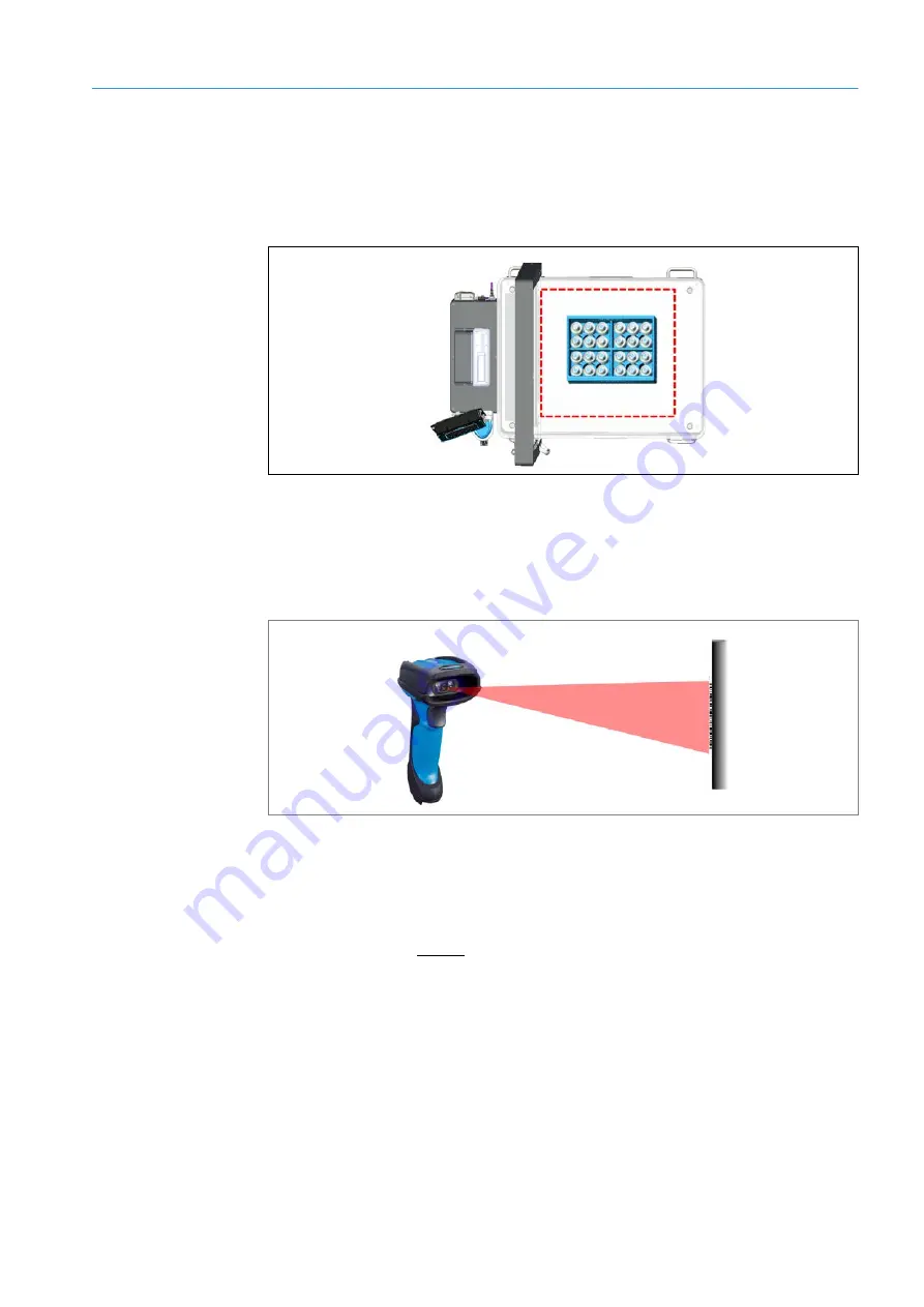
Placing an object in the measurement field
The measurement object is placed in the clear-glass area of the glass plate. This area
marks the measurement field, i.e., the area in which the object can be captured by the
light grids. If the object, or any part of it, is outside of the measurement field (in the opal
glass area) an error message will be issued.
Fig. 15: Marked measurement field on the glass panel
Bar code reading (only for operating mode with bar code scanning)
The wired hand-held scanner identifies the object and transmits the shipping number to
the controller. The scanner creates a scan line on the object to read the bar code using a
red light. The bar code that is read is then shown on the display.
Fig. 16: Operating principle – bar code reading
The bar code can also be entered manually using the display.
Weight measurement (only for operating mode with bar code scanning)
In the operating mode without bar code scanning, the measuring process starts with the
system detecting a stable weight value. Bar codes cannot be scanned or processed.
Note


