2
Flexi Soft safety controller
3
Signal for interlocking device
4
Actuator status signal
Implementation with the Flexi Classic safety controller
Prerequisites
If you connect locks to the safe sensor cascade and wish to integrate them into a Flexi
Classic safety controller, you must use the Flexi Loop MSTR2 accessory. Use its stand‐
ard I/O functions with factory settings without data communication via IO-Link (
"Operating principle on Flexi Classic", page 17
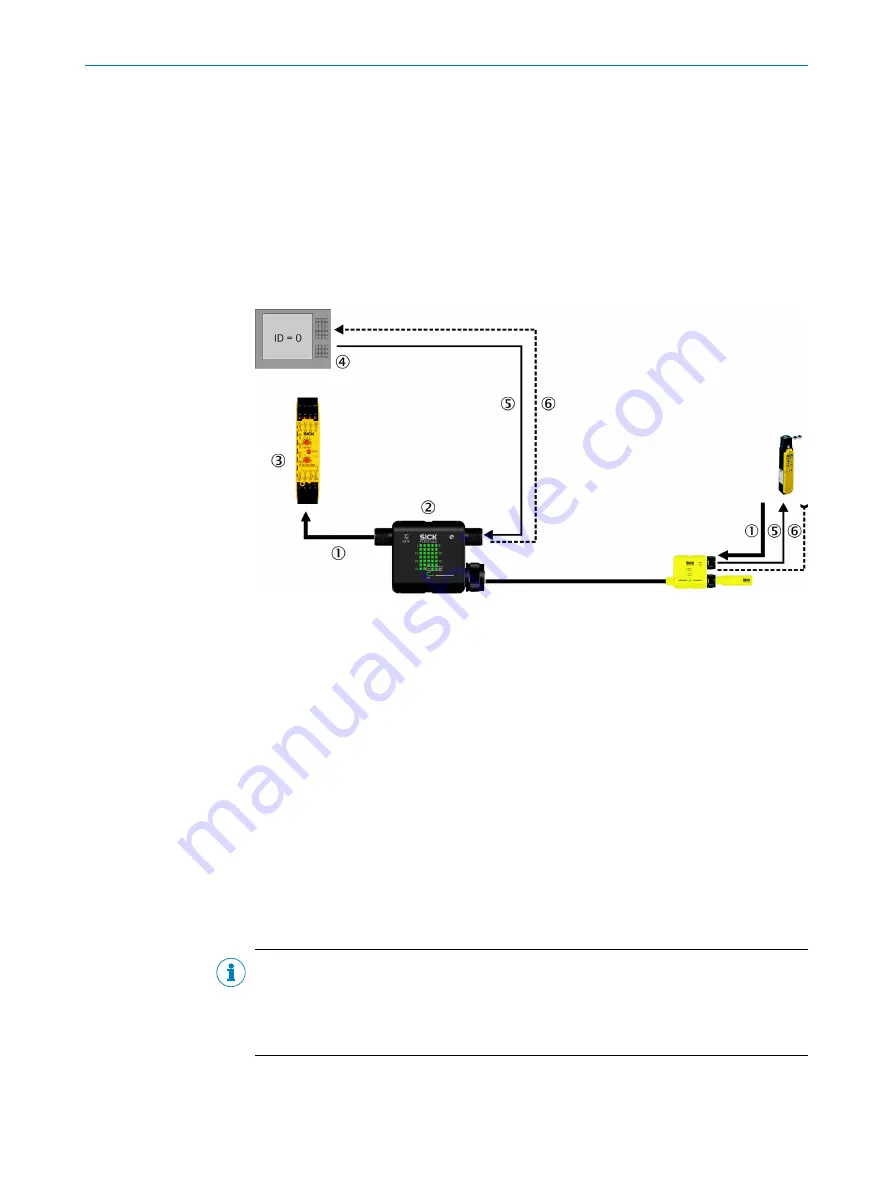
Figure 35: Locking device with the Flexi Classic safety controller
1
Safe cut-off path (position monitoring for the protective device and the interlocking)
2
MSTR2 Flexi Loop accessory
3
Flexi Classic safety controller
4
Locking device application (e.g. in a PLC)
5
Signal for interlocking
6
Optional: actuator status signal
Connect the signal for interlocking your application to the AUX_IN non-safe input of the
Flexi Loop MSTR2 accessory. The safe sensor cascade forwards the signal to the non-
safe outputs of the Flexi Loop nodes, where it deactivates the lock's connected inter‐
locking device.
The AUX_IN non-safe input of the Flexi Loop MSTR2 accessory is factory-set to affect all
AUX_OUT non-safe outputs of the Flexi Loop nodes. If you wish to use AUX_OUT non-
safe outputs of individual Flexi Loop nodes for purposes other than to connect a lock,
then switch off the
AUX_OUT from MSTR AUX_IN
parameter for this node via IO-Link (
"Configuration of the Flexi Loop nodes", page 58
NOTE
On all Flexi Loop nodes FLN-EMSS1100108 with locking device connected, leave the
non-safe input AUX_IN unused or make a connection to GND
6
. Otherwise the output
monitoring activated in the factory configuration on all Flexi Loop nodes will intervene in
the switching behavior of the non-safe outputs AUX_OUT.
4
DESIGN
38
O P E R A T I N G I N S T R U C T I O N S | Flexi Loop
8015836/YT10/2016-05-24 | SICK
Subject to change without notice


