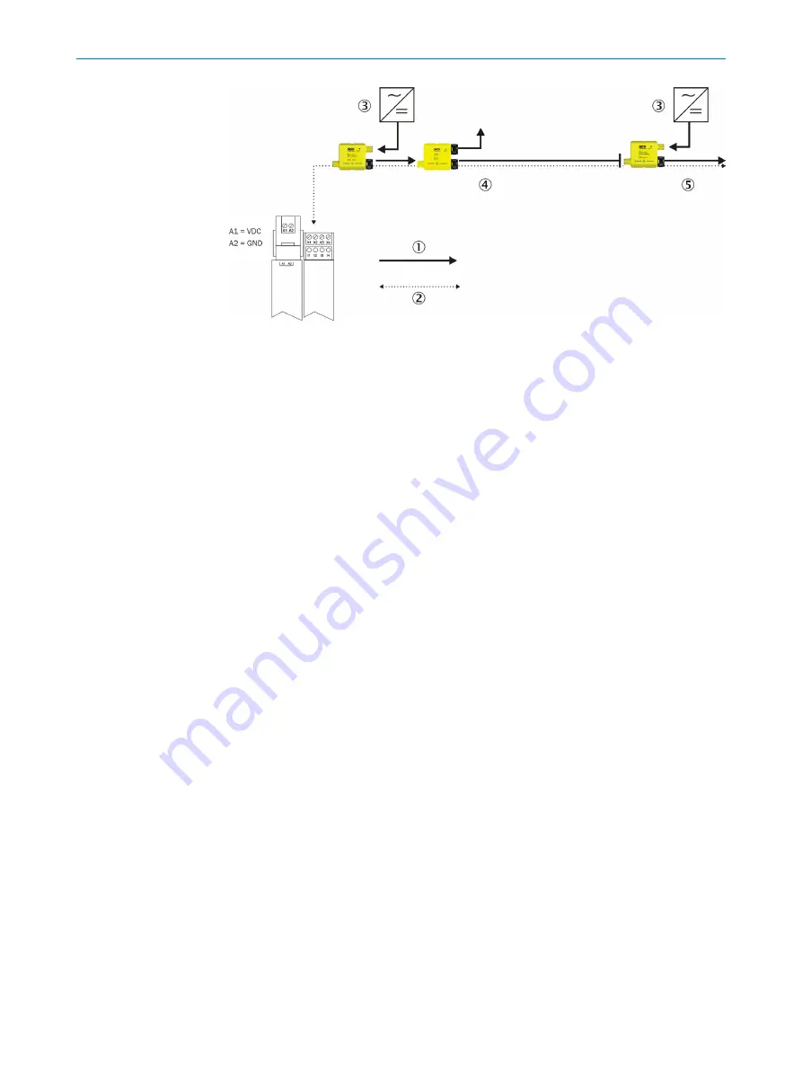
Figure 30: Division into sections
1
Power flow
2
Data flow
3
Power supplies
4
Section 1 max. 4 A
5
Section 2 max. 4 A
The PWRI power supply accessory monitors the current in the individual Flexi Loop sec‐
tions and shuts down in case of overcurrent. In addition the operating voltage in each
section is monitored.
The power supply for the next Flexi Loop node and the sensors connected to the node is
electrically isolated from the previous Flexi Loop node by the power supply accessory.
4.2
Voltage drop via cables, Flexi Loop nodes and Flexi Loop accessories
The voltage VDC must be present at each input on a Flexi Loop node and a Flexi Loop
accessory in the range from 16.8 … 30 V DC!
The voltage drop over the safe sensor cascade is dependent on the following factors:
•
number of Flexi Loop nodes (internal power consumption)
•
current consumption of the sensors and actuators connected
•
length of the cables
•
cross-section of the wire
•
ambient temperature
4.2.1
Examples for the voltage drop
In the following examples an input voltage of 24 V DC is assumed.
Number of nodes
The first examples show how the voltage drop behaves in relation to the number of Flexi
Loop nodes. The examples assume that there are no devices connected to the Flexi
Loop nodes, instead that power only flows due to internal consumption of the nodes
(e.g. on exclusive operation with Flexi Loop nodes of type FLN-EMSS0000105).
The following table shows that although the voltage reduces at the individual Flexi Loop
nodes due to the voltage drop, it is still high enough at the 10
th
Flexi Loop node.
DESIGN
4
8015836/YT10/2016-05-24 | SICK
O P E R A T I N G I N S T R U C T I O N S | Flexi Loop
31
Subject to change without notice


