ADJUSTMENT
1 - 70
1.14.2
PFP paper sizes
Before the copier is shipped from the factory, A4-R, A3 and B4 (LT-R, LG and LD) are set to the
upper, middle and lower cassettes, respectively. The following procedure describes how to change
the paper sizes of the cassettes in accordance with a request from the user.
Note:
Since the PFP upper is not usable for B5 size paper, do not change its size to B5.
Mechanical Modifications
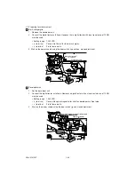
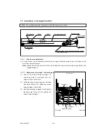
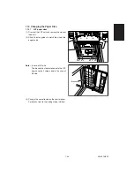
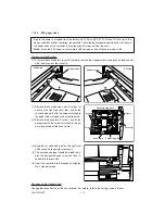
(1) Draw out the cassette that you want to modify, remove the stopper screws (one each on feed and exit
side), and draw out the cassette.
(2) Remove the cassette side walls (2 screws for
each) on the front and rear sides, and fix the
cassette side walls with the screws matched to
the paper size marked on the cassette guide.
(3) Remove the back plate (1 screw), and fix the
back plate with the screws matched to the pa-
per size marked on the base frame.
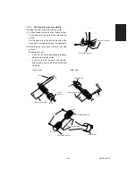
(4) Slide the cassette size label on the right front
of the cassette to upward to remove it.
(5) The cassette size label should be folded to dis-
play the designated paper size, and then in-
serted into the cassette.
(6) Insert the cassette into the feeder, and tighten
the 2 stopper screws.
Stopper screw
Feed side
Stopper screw
Exit side
Cassette side walls
Screws
Screw
Screws
Cassette
Cassette guide
Back plate
Changes on the Control Panel
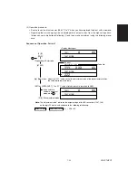
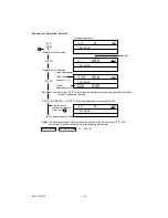
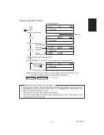
Change the cassette size on the control panel. For details, refer to the setting mode (08) item.
Содержание AR-650
Страница 103: ...MAINTENANCE 2 6 Rear drive system 38 36 37 3 54 54 54 54 54 54 96 12 81 63 63 46 ...
Страница 104: ...2 7 MAINTENANCE ADF front sectional view 100 104 109 105 106 102 108 99 101 103 107 98 ...
Страница 118: ...SUPPLIES 3 6 9 REMOVE 1 1 2 10 REMOVE 11 TURN OVER 13 REMOVE 15 REMOVE 14 REMOVE 12 REMOVE 16 INSTALL 2 2 1 ...
Страница 119: ...3 7 SUPPLIES 18 INSTALL 2 1 19 INSTALL 2 1 20 CONNECT 21 INSTALL 2 2 2 1 22 CLOSE 1 3 2 23 INSTALL 17 CONNECT ...
Страница 122: ...SUPPLIES 3 10 13 CONNECT 15 CLOSE 2 1 14 CLOSE 1 2 16 TURN ON 17 PRESS 18 END ...
Страница 125: ...3 13 SUPPLIES 5 OPEN 2 1 6 DISCONNECT 7 REMOVE 2 1 9 8 REPLACE 2 1 9 INSTALL 1 2 10 CONNECT 11 CLOSE 1 2 12 CLOSE 2 1 ...
Страница 126: ...SUPPLIES 3 14 13 TURN ON 14 PRESS 15 END 5 DEVELOP UNIT 1 REMOVE 3 2 3 5 4 2 REMOVE 3 INSTALL 4 FILL 5 INSTALL 10 ...
Страница 168: ...Select Direct Connection and then click Next button Select Communications Port COM1 and then click Next button 5 4 ...
Страница 169: ...Click Finish button then Virtual Modem installation is completed 5 5 ...
Страница 179: ...To make the connection ONLINE mode click button before firmware downloading 5 15 ...
Страница 194: ......
Страница 195: ...MEMO ...
Страница 196: ...MEMO ...
Страница 197: ...MEMO ...
Страница 198: ...MEMO ...
Страница 199: ...MEMO ...

