7.4.2
Implementation Possibilities with IPOS
Generally different possibilities of carrying out a positioning operation via fieldbus arise. The following
variants, for example, can be implemented with IPOS:
– The fieldbus position setpoint is used as IPOS-manual operation-setpoint.
– The fieldbus position setpoint is used for the command GOPA in the IPOS automatic program.
– The fieldbus position setpoint is mapped to IPOS-variable and can be used universally.
– Virtual terminals of the control word 2 are used as pointers to the positioning table.
7.4.3
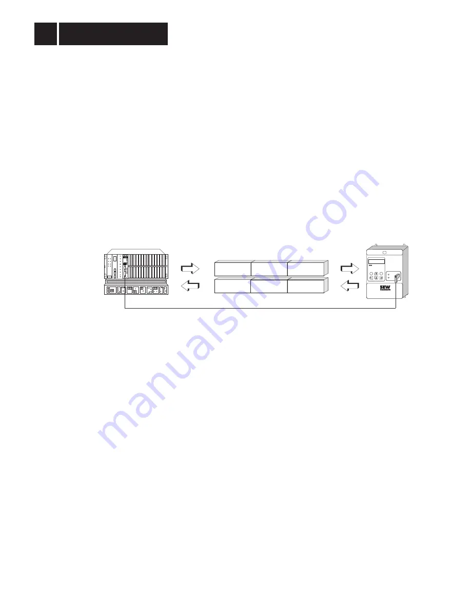
Process Data Description for Positioning Mode
As, in this example, the inverter is to receive control commands as well as the position setpoints, the
process data length must be set to 3PD (Fig. 63). The largest application variety is achieved with the
following process output data description, which can also be implemented in this example:
P560
Setpoint description PO1 control word 2
P562
Setpoint description PO2 position high
P564
Setpoint description PO3 position low
While for the transfer of the position setpoints
position high as well as position low must be
programmed, the actual value description can be set at will.
For this application example the process input data is described as follows:
P561
Actual value description PI1 status word 2
P563
Actual value description PI2 position high
P565
Actual value description PI3 position low
With this setting you have the possibility to constantly evaluate the current actual position as well as
further status information of the drive via the process data channel.
With the virtual terminals of the control word 2 and the status word 2 a direct connection between
the higher-level automation device (fieldbus master) and the IPOS automatic program decentrally
executed in the inverter. Therefore the virtual input and output terminals can be directly processed
and controlled in the IPOS program. In this case the digital input and output terminals of the options
FEA 31 or FIO 31 respectively, which are physically not available with the fieldbus option inserted,
are projected onto the fieldbus system as virtual terminals within the control word 2 and the status
word 2 (Fig. 64).
MO
VI
TR
AC
®
841
E
Q
RUN
BUS
FAULT
Position High
Position High
Position Low
Position Low
FIELDBUS
CONTROL MODE
Status
word 2
Control
word 2
Process input data (PI)
Process output data (PO)
01148AEN
Fig. 63: Application example for position specification via fieldbus
Application Examples
7
72
MOVITRAC
®
31.. Fieldbus Unit Profile
Phone: 800.894.0412 - Fax: 888.723.4773 - Web: www.clrwtr.com - Email: [email protected]


