For safety reasons the definition of the basic control block is such that the inverter adopts a safe state
(
No Enable) when a control word containing 0000hex is given, as all common fieldbus master systems
definitely reset the outputs to 0000hex in the case of a fault or malfunction. In this case the inverter
will carry out a rapid stop and then activate the mechanical brake.
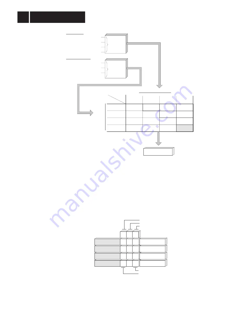
Controlling the Inverter with a 0-2 Bit
When the inverter has been enabled via the terminals, it can be controlled with bit 0 - bit 2 of the
basic control block. These three bits are used to activate four different control commands for inverter
control through the fieldbus system (Fig. 13).
Setpoint processing
Enable
Contr. inhibit
Rapid stop
Stop
Enable
Stop
Contr. inhibit
Rapid stop
Stop
Stop
Rapid stop
Contr. inhibit
Rapid stop
Rapid stop
Rapid stop
Controller inhibit
Controller inhibit
Controller inhibit
Controller inhibit
Controller inhibit
Controller inhibit
Rapid stop
Stop
Enable
Control word command:
Terminal processing function
Bit 0: controller inhibit/enable
Bit 1: enable/rapid stop
Bit 2: enable/stop
Fieldbus control word:
CW/STOP
CCW/STOP
ENABLE
/CONTOLLER INHIBIT
Input terminals:
control word
processing
terminal
processing
00322AEN
Fig. 12: Connecting the safety-relevant control signals from the input terminals and the fieldbus
Bit 2
X
X
0
1
Bit 1
X
0
1
1
Bit 0
1
0
0
0
Bit 2: enable/stop
Bit 1: enable/rapid stop
Bit 0: controller inhibit/enable
X = irrelevant
highest priority
lowest priority
e.g. 06hex
e.g. 02hex
e.g. 00hex, 04hex
e.g. 01hex, 03hex,
05hex, 07hex
Controller inhibit:
Rapid stop:
Stop:
Enable:
Control command
00323AEN
Fig. 13: Coding of the control commands of the MOVITRAC
®
31.. inverter
Inverter Control
with Process Data
3
26
MOVITRAC
®
31.. Fieldbus Unit Profile
Phone: 800.894.0412 - Fax: 888.723.4773 - Web: www.clrwtr.com - Email: [email protected]


