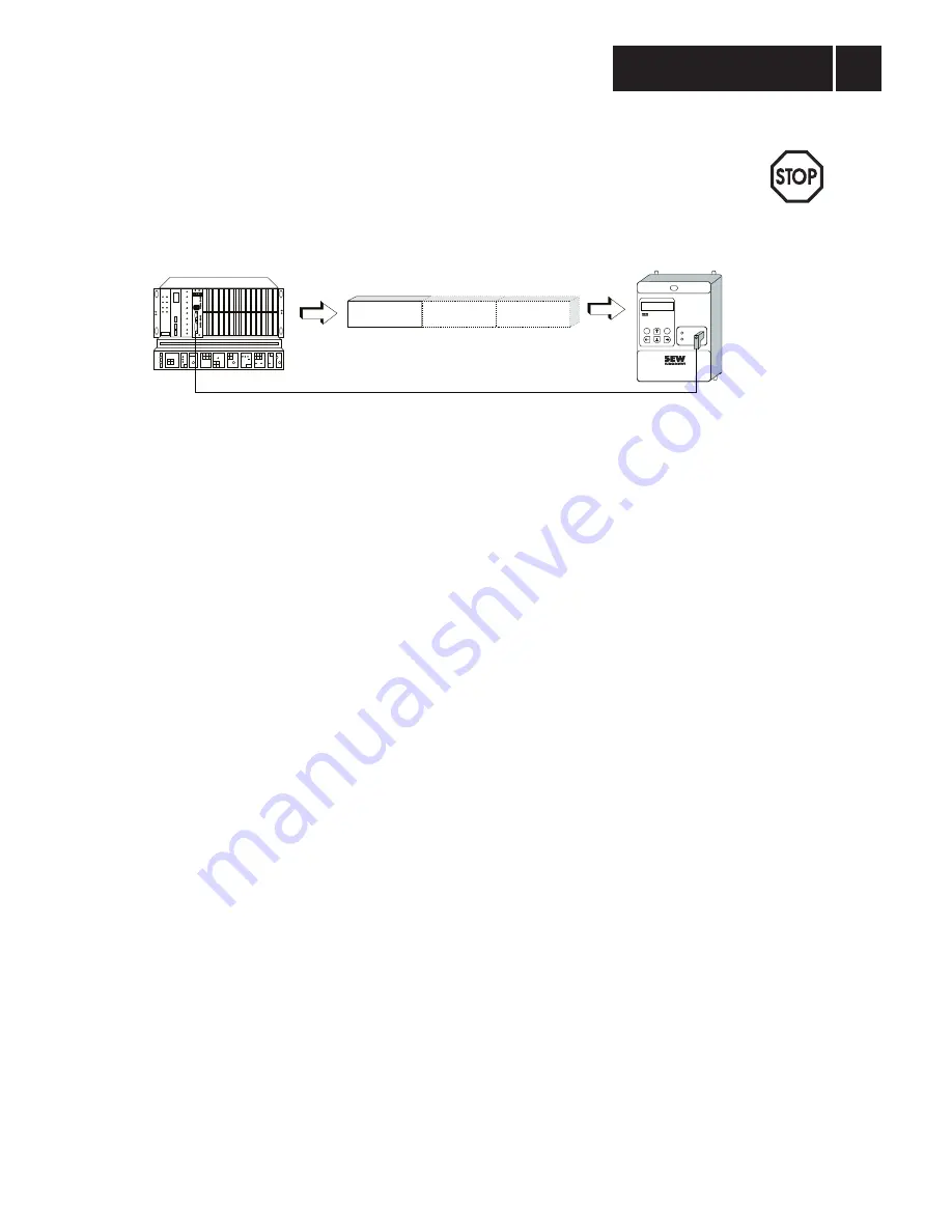
CAUTION!
When handling the position setpoints in the application program of the higher-level automation unit,
make sure that both process output data words containing the position data are dealt with
consistently, i.e. that the position setpoint high is always transmitted together with the position
setpoint low! Otherwise the inverter might approach undefined positions, as e.g. an old position
setpoint low and a new position setpoint high might be active together!
Speed Limit (MAX. SPEED)
The
Setpoint Description POx = MAX. SPEED setting causes the MOVITRAC
®
31.. inverter to interpret
the transmitted setpoint as speed limit. The speed limit is therefore specified in the unit [1/min] and
interpreted as absolute value for both directions of rotation. The supported range of values for the
fieldbus speed limit corresponds to the range of values for the
P202 F-MAX 1 parameter. If the speed
is below this range of values the minimum will become effective, if it exceeds the set range, the
maximum of the set limit value will become effective. Scaling of the speed limit see Section 3.3.5.
Entering the speed limit via the fieldbus will automatically deactivate parameters
P202 F-MAX 1, P212 F-MAX 2 and P222 F-MAX 3 !
The speed limit value specified via the process output data is generally active.
Current Limit (MAX. CURRENT)
The
Setpoint Description POx = MAX. CURRENT setting causes the MOVITRAC
®
31.. inverter to
interpret the transmitted process output data as current limit. The current limit is specified in per cent
of the inverter rated current in the unit [% In] and is interpreted as absolute value for both directions
of rotation. The supported range of values for the fieldbus current limit corresponds to the range of
values for parameter
P320 I-MAX 1. If the current is below this range of values, the minimum will
become effective, if it exceeds the set range, the maximum of the set limit value will become effective.
Scaling of the current limit see Section 3.3.5.
Entering the current limit via the fieldbus will automatically deactivate parameters
P320 I-MAX 1 and
P340 I-MAX 2.
M
O
VI
TRAC
®
841
E
Q
RUN
BUS
FAULT
PD1
PD2
PD3
Fieldbus
CONTROL MODE
Process output data (PO)
Position High Position Low
Control word 1
00317AEN
Fig. 7: Assigning a position setpoint to the process output data
3
Inverter Control
with Process Data
MOVITRAC
®
31.. Fieldbus Unit Profile
15
Phone: 800.894.0412 - Fax: 888.723.4773 - Web: www.clrwtr.com - Email: [email protected]


