


64
Manual – MOVI-PLC® Application Solution "SyncCrane"
6
Automatic mode
Operation
6.6.1
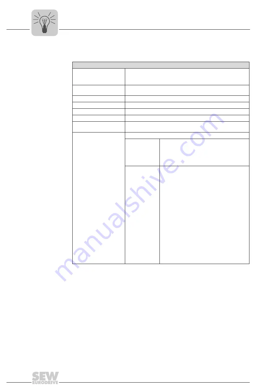
Interface description
Interface description
Mode selection
PO1:Bit11 = FALSE
PO1:Bit12 = FALSE
PO1:Bit13 = TRUE
Mode selection virtual
encoder
See description jog mode/positioning mode (supplement virtual encoder)
Start
PO1:8
Axis number
PO3 Broadcast 99
Position setpoint
PO6 and PO7 virtual master encoder position
Position limiting
Startup parameter limitation of virtual master encoder
Ramp specification
•
PO9 acceleration ramp [ms]
•
PO10 deceleration ramp [ms]
Brief description
The entire system is moved synchronously in automatic mode.
Prerequisite
•
Operating mode is selected and start is set
•
Drive is enabled
•
No axis fault present
•
No lag error
•
No external encoder error
•
No error on PI1:Bit 6
Functional
description
Automatic mode enables the user to operate the axis
system synchronously.
After selecting automatic mode or upon changing to
the inverter status "A", the slave axes are adjusted to
a calculated "adjust position". The slave axes signal
a completed adjustment process via feedback bit
PO2:Bit4 "Axes synchronous".
From this time on, the axis system can be moved by
controlling the virtual encoder. This is done by
activating PO2 and
jog mode
or
positioning mode
.
The axis system follows the actual value of the
virtual encoder according to the principle of indirect
synchronization. This means the setpoint is
converted for the motor encoder to a position
setpoint of the internal synchronous operation. At
the same time, slip is compensated by monitoring
the external encoder position. The slave axes signal
during the movement whether a lag warning error
was issued by means of feedback bits.
Refer to the following chapters for detailed informa-
tion on the
adjustment mode
and
synchronization
functions.
Содержание MOVI-PLC
Страница 2: ...SEW EURODRIVE Driving the world ...
Страница 105: ......
Страница 106: ......
Страница 107: ...SEW EURODRIVE Driving the world ...