Maintenance
9711QOR-86 C & Ku-Band TXRX
19-2
19.2.
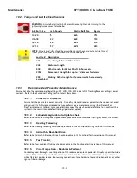
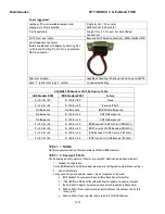
Torque and Loctite Specifications
WARNING:
Assure that all nut & bolt assemblies are tightened according to the
tightening torque values listed below:
SAE Bolt Size
Inch Pounds
Metric Bolt Size
Kg-cm
1/4-20
75
M6
75.3
5/l6-18
132
M8
150
3/8-16
236
M10
270
1/2-13
517
M12
430
NOTE:
All nuts and bolts should be assembled using the appropriate Loctite thread-
locker product number for the thread size of the hardware.
Loctite # Description
223
Low strength for small fasteners.
242
Medium strength
638
High strength for Motor Shafts & Sprockets.
2760
Permanent strength for up to 1” diameter fasteners.
290
Wicking, High strength for fasteners which are already
assembled.
19.3.
Recommended Preventive Maintenance
Ensure that all of the normal operating settings (LAT, LON, HDG, SAT and al of the Tracking Receiver settings) are set
correctly. Refer to the Functional Testing section to test the system.
19.3.1.
Check ACU Parameters
Assure that the parameters are set correctly. Once all system and receiver parameters have been set, saved
and verified it is highly recommended that you perform a parameter dump using either DacRemP or
ProgTerm diagnostic software to save an electronic copy that may be used a later time to re-configure the
system to the commissioned default settings (parameter upload).
19.3.2.
Latitude/Longitude Auto-Update check
Refer to the Latitude & Longitude Update check procedure in the Functional Testing section of this manual.
19.3.3.
Heading Following
Refer to the Heading Following verification procedure in the Functional Testing section of this manual.
19.3.4.
Azimuth & Elevation Drive
Refer to the Azimuth & Elevation Drive check procedure in the Functional Testing section of this manual.
19.3.5.
Test Tracking
Refer to the four quadrant Tracking check procedure in the Functional Testing section of this manual.
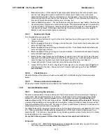
19.3.6.
Visual Inspection - Radome & Pedestal
Conduct a good, thorough, visual inspection of the radome and antenna pedestal. Visually inspect the inside
surface of the radome top and of the antenna pedestal. Look for water or condensation, rust or corrosion,
white fiberglass powder residue, loose wiring connections, loose hardware, loose or broken belts or any other
signs of wear or damage.
Содержание 9711QOR-86
Страница 4: ......
Страница 13: ...Table of Contents xiii 23 1 9711QOR 86 MODEL SPECIFIC DRAWINGS 23 1 23 2 9711 GENERAL DRAWINGS 23 1 ...
Страница 14: ...Table of Contents xiv This Page Intentionally Left Blank ...
Страница 26: ...Site Survey 9711QOR 86 C Ku Band TXRX 2 8 This Page Intentionally Left Blank ...
Страница 70: ...Installation 9711QOR 86 C Ku Band TXRX 3 44 This Page Intentionally Left Blank ...
Страница 74: ...Basic Setup of the ACU 9711QOR 86 C Ku Band TXRX 4 4 This Page Intentionally Left Blank ...
Страница 78: ...Setup Ships Gyro Compass 9711QOR 86 C Ku Band TXRX 6 2 This Page Intentionally Left Blank ...
Страница 80: ...Setup Band Reflector Select 9711QOR 86 C Ku Band TXRX 7 2 This Page Intentionally Left Blank ...
Страница 86: ...Setup Home Flag Offset 9711QOR 86 C Ku Band TXRX 9 4 This Page Intentionally Left Blank ...
Страница 90: ...Setup Targeting 9711QOR 86 C Ku Band TXRX 10 4 This Page Intentionally Left Blank ...
Страница 96: ...Setup Searching 9711QOR 86 C Ku Band TXRX 11 6 This Page Intentionally Left Blank ...
Страница 122: ...Antenna Specific Operation 9711QOR 86 C Ku Band TXRX 16 12 This Page Intentionally Left Blank ...
Страница 126: ...Functional Testing 9711QOR 86 C Ku Band TXRX 17 4 This Page Intentionally Left Blank ...
Страница 142: ...Installation Troubleshooting 9711QOR 86 C Ku Band TXRX 18 16 This Page Intentionally Left Blank ...
Страница 188: ...9711QOR 86 Technical Specifications 9711QOR 86 C Ku Band TXRX 22 8 This Page Intentionally Left Blank ...
Страница 190: ...Drawings 9711QOR 86 C Ku Band TXRX 23 2 This Page Intentionally Left Blank ...
Страница 196: ......
Страница 199: ......
Страница 233: ......
Страница 234: ......
Страница 239: ......
Страница 241: ......
Страница 243: ......


