9711QOR-86 C & Ku-Band TXRX
Maintenance
19-25
10.
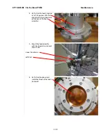
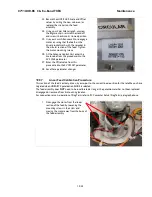
Carefully engage the sprockets by
moving the potentiometer in toward the
body of the feed and tightening the
mounting nut on the underside of the
bracket while holding the body of the
potentiometer firmly in place.
11.
Once the potentiometer is engaged, type
“u” and verify the potentiometer reading
is still within 1190 +/- 30.
12.
Tighten the mounting nut to secure the
pot and verify the potentiometer reading
is still within 1190 +/- 30.
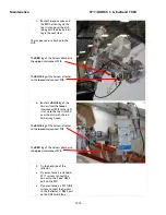
13.
If not, loosen the mounting nut on the
underside of the bracket and rotate the
body of the potentiometer slightly while
displaying the value. Continue rotating
the body of the potentiometer until
reading is within 1190 +/- 30. Tighten
the nut while holding the body of the
potentiometer firmly in place and verify
that the displayed value is acceptable.
Repeat until acceptable reading is
obtained.
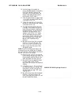
14.
Record the 4 digit value that is displayed
after the “U” as your CCW value. This
value will be used in calculations below.
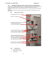
15.
Remove your 2mm Allen wrench from
the alignment holes.
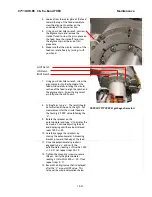
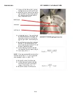
NOTE: The CW & CCW alignment holes in the
collar under the driven sprocket are 180 degrees
apart and should be scribe marked on the body of
the OMT, above the driven sprocket.
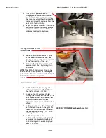
16.
Rotate the linear section of the feed CW
by hand to align the alignment hole in the
driven sprocket with the CW hole in the
collar underneath the driven sprocket.
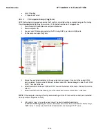
17.
Ensure both holes are aligned and insert
your 2mm Allen wrench into the
alignment holes to prevent the feed from
rotating.
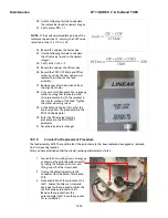
18.
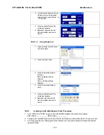
In ProgTerm, type “u”. The result should
be formatted as shown to the right. Pot
measurements for the linear section of
the feed are the four digit “YYYY” value
following the “U”.
19.
Record the 4 digit value that is displayed
after the “U” as your CW value. This
value (typically approximately 2337) will
be used in calculations below.
GXXXXUYYYYVZZZZ<garbage character>
Содержание 9711QOR-86
Страница 4: ......
Страница 13: ...Table of Contents xiii 23 1 9711QOR 86 MODEL SPECIFIC DRAWINGS 23 1 23 2 9711 GENERAL DRAWINGS 23 1 ...
Страница 14: ...Table of Contents xiv This Page Intentionally Left Blank ...
Страница 26: ...Site Survey 9711QOR 86 C Ku Band TXRX 2 8 This Page Intentionally Left Blank ...
Страница 70: ...Installation 9711QOR 86 C Ku Band TXRX 3 44 This Page Intentionally Left Blank ...
Страница 74: ...Basic Setup of the ACU 9711QOR 86 C Ku Band TXRX 4 4 This Page Intentionally Left Blank ...
Страница 78: ...Setup Ships Gyro Compass 9711QOR 86 C Ku Band TXRX 6 2 This Page Intentionally Left Blank ...
Страница 80: ...Setup Band Reflector Select 9711QOR 86 C Ku Band TXRX 7 2 This Page Intentionally Left Blank ...
Страница 86: ...Setup Home Flag Offset 9711QOR 86 C Ku Band TXRX 9 4 This Page Intentionally Left Blank ...
Страница 90: ...Setup Targeting 9711QOR 86 C Ku Band TXRX 10 4 This Page Intentionally Left Blank ...
Страница 96: ...Setup Searching 9711QOR 86 C Ku Band TXRX 11 6 This Page Intentionally Left Blank ...
Страница 122: ...Antenna Specific Operation 9711QOR 86 C Ku Band TXRX 16 12 This Page Intentionally Left Blank ...
Страница 126: ...Functional Testing 9711QOR 86 C Ku Band TXRX 17 4 This Page Intentionally Left Blank ...
Страница 142: ...Installation Troubleshooting 9711QOR 86 C Ku Band TXRX 18 16 This Page Intentionally Left Blank ...
Страница 188: ...9711QOR 86 Technical Specifications 9711QOR 86 C Ku Band TXRX 22 8 This Page Intentionally Left Blank ...
Страница 190: ...Drawings 9711QOR 86 C Ku Band TXRX 23 2 This Page Intentionally Left Blank ...
Страница 196: ......
Страница 199: ......
Страница 233: ......
Страница 234: ......
Страница 239: ......
Страница 241: ......
Страница 243: ......

