


9711QOR-86 C & Ku-Band TXRX
Installation Troubleshooting
18-3
heading) go to step 2. If it moves in the correct direction but does not display the correct heading go to step
3. The gyro compass connects to the Terminal Mounting Strip on TB3- R1, R2, S1, S2 and S3.
CAUTION - Electrical Shock Potentials exist on the Gyro
Compass output lines. Assure that the Gyro Compass output is
turned OFF when handling and connecting wiring to the
Terminal Mounting Strip.
1.
The Ships Heading display does not change when the ship changes direction. Using a multimeter
read between R1 and R2. It should read 115 VAC. If it does not then a fuse is blown at the gyro
repeater or there is an open between the repeater and the ACU. Read between S1 and S2, S2 and
S3 and finally S3 and S1. They should all read between 0 and 90 VAC. The voltage level will change
as the ship turns. If one reading is very close to 0 volts wait until the ship has made a major change
in heading and then check voltage again. If the reading is still very low there is a problem in the line
between the gyro repeater and the ACU or a problem in the gyro repeater itself.
2.
The display changes in the direction opposite of the movement of the ship. Switch the secondary
leads S1 and S2. Caution: there is 90 VAC between them! Verify that when the ship changes
direction the display shows change in the same direction. If the direction is correct but the heading
is incorrect go to step C.
3.
If the ship's heading is different than the bridge, select the HDG function in the SHIP display mode
by pressing the SHIP key 4 times. Key in the correct heading using the numeric keys and press
ENTER.
18.3.
Troubleshooting
18.3.1.
Theory Of Stabilization Operation
The antenna system is mounted on a three axis stabilization assembly that provides free motion with 3
degrees of freedom. This assembly allows the inertia of the antenna system to hold the antenna pointed
motionless in inertial space while the ship rolls, pitches and yaws beneath the assembly. Three low friction
torque motors attached to each of the three free axes of the assembly provide the required force to
overcome the disturbing torque imposed on the antenna system by cable restraints, bearing friction and small
air currents within the radome. These motors are also used to re-position the antenna in azimuth and
elevation.
The Pedestal Control Unit (PCU) uses inputs from the level cage sensors to calculate the amount of torque
required in each axis to keep the antenna pointed /-0.2 degrees. The primary sensor input for each
loop is the rate sensor mounted in the Level Cage Assembly. This sensor reports all motion of the antenna to
the PCU. The PCU immediately responds by applying a torque in the opposite direction to the disturbance to
bring the antenna back to its desired position. Both the instantaneous output of the rate sensor (Velocity
Error) and the integrated output of the rate sensor (Position Error) are used to achieve the high pointing
accuracy specification.
The calculated torque commands are converted to a 5 volt differential analog signal by a Digital to Analog
converter (D/A) and sent to each of three Brush-Less Servo Amplifiers. These amplifiers provide the proper
drive polarities and commutation required to operate the Brush-Less DC Servo Motors in torque mode. The
Torque acting on the mass of the antenna cause it to move, restoring the rate sensors to their original
position, and closing the control loop.
Since the rate sensors only monitor motion and not absolute position, a second input is required in each axis
as a long term reference to keep the antenna from slowly drifting in position. The Level and Cross Level
reference is provided by a two axis tilt sensor in the level cage assembly. The Azimuth reference is provided
by combining the ships gyro compass input and the antenna relative position.
18.3.2.
Series 9711QOR Antenna Initialization
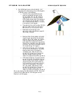
Turn the pedestal power supply ON. The brakes on the Elevation and Cross-Level motors will release. A brake
release power supply control circuit supplies 24 VDC to the brakes initially (5-10 seconds) and then reduces
the voltage to 12VDC. The PCU will initialize the stabilized portion of the mass to be level with the horizon
and at a prescribed Azimuth and Elevation angles in the specific sequence of steps listed below.
Содержание 9711QOR-86
Страница 4: ......
Страница 13: ...Table of Contents xiii 23 1 9711QOR 86 MODEL SPECIFIC DRAWINGS 23 1 23 2 9711 GENERAL DRAWINGS 23 1 ...
Страница 14: ...Table of Contents xiv This Page Intentionally Left Blank ...
Страница 26: ...Site Survey 9711QOR 86 C Ku Band TXRX 2 8 This Page Intentionally Left Blank ...
Страница 70: ...Installation 9711QOR 86 C Ku Band TXRX 3 44 This Page Intentionally Left Blank ...
Страница 74: ...Basic Setup of the ACU 9711QOR 86 C Ku Band TXRX 4 4 This Page Intentionally Left Blank ...
Страница 78: ...Setup Ships Gyro Compass 9711QOR 86 C Ku Band TXRX 6 2 This Page Intentionally Left Blank ...
Страница 80: ...Setup Band Reflector Select 9711QOR 86 C Ku Band TXRX 7 2 This Page Intentionally Left Blank ...
Страница 86: ...Setup Home Flag Offset 9711QOR 86 C Ku Band TXRX 9 4 This Page Intentionally Left Blank ...
Страница 90: ...Setup Targeting 9711QOR 86 C Ku Band TXRX 10 4 This Page Intentionally Left Blank ...
Страница 96: ...Setup Searching 9711QOR 86 C Ku Band TXRX 11 6 This Page Intentionally Left Blank ...
Страница 122: ...Antenna Specific Operation 9711QOR 86 C Ku Band TXRX 16 12 This Page Intentionally Left Blank ...
Страница 126: ...Functional Testing 9711QOR 86 C Ku Band TXRX 17 4 This Page Intentionally Left Blank ...
Страница 142: ...Installation Troubleshooting 9711QOR 86 C Ku Band TXRX 18 16 This Page Intentionally Left Blank ...
Страница 188: ...9711QOR 86 Technical Specifications 9711QOR 86 C Ku Band TXRX 22 8 This Page Intentionally Left Blank ...
Страница 190: ...Drawings 9711QOR 86 C Ku Band TXRX 23 2 This Page Intentionally Left Blank ...
Страница 196: ......
Страница 199: ......
Страница 233: ......
Страница 234: ......
Страница 239: ......
Страница 241: ......
Страница 243: ......